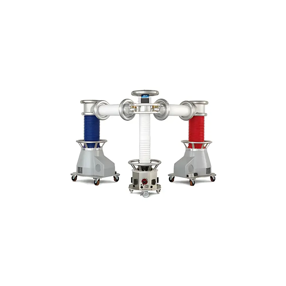
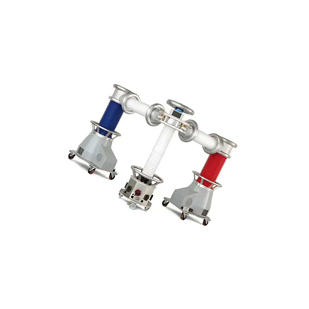
B2 HVA200 Ultra-Low Frequency (VLF) Cable Test System
| Brand | B2 |
|---|---|
| Origin | Austria |
| Model | HVA200 |
| Output Voltage | 200 kV peak (140 kV rms) sinusoidal VLF |
| DC Voltage | ±200 kV |
| Output Current | up to 140 mA |
| Maximum Capacitive Load | 6 µF at 140 kV rms |
| Output Power | 7.2 kVA |
| Frequency Range | 0.01–0.1 Hz |
| Input | 3P+N+PE, 230/400 VAC, 48–62 Hz, 9 kVA |
| Dimensions (L×H×W) | 430 × 230 × 120 cm |
| Weight | <900 kg |
| Operating Temperature | −10 °C to +45 °C |
| Storage Temperature | −25 °C to +70 °C |
| Humidity | 5–85% non-condensing |
| Ingress Protection | IP22 |
| Interface | Optical fiber and USB |
Overview
The B2 HVA200 Ultra-Low Frequency (VLF) Cable Test System is an engineered high-voltage diagnostic platform designed for field and laboratory-based condition assessment of medium- and high-voltage extruded insulation cables—particularly cross-linked polyethylene (XLPE) and ethylene propylene rubber (EPR) systems. Operating in the standardized VLF range of 0.01–0.1 Hz (per IEEE 400.2, IEC 60502-2, and CIGRÉ TB 495), the system applies a controlled sinusoidal or DC stress waveform to evaluate dielectric integrity without inducing thermal overstress or irreversible insulation damage associated with power-frequency AC testing. Its 200 kV peak / 140 kV rms sinusoidal output capability represents one of the highest VLF voltage ratings commercially available for portable cable test systems, enabling full-length withstand verification of transmission-class cables rated up to 145 kV (Um). The system complies with international test protocols for acceptance, routine, and diagnostic testing—including VLF withstand, sheath integrity verification, and combined VLF-PD or tan δ measurements when extended with optional modules.
Key Features
- Multi-mode high-voltage generation: Fully regulated sinusoidal VLF (0.01–0.1 Hz) and polarity-selectable DC (±200 kV), both operating independently of load capacitance—ensuring stable waveform fidelity across cable lengths up to 25 km (at typical 0.2–0.3 µF/km).
- High-power output architecture: 7.2 kVA continuous-rated output with 140 mA maximum current supports testing of large-capacitance networks (up to 6 µF at 140 kV rms), eliminating duty-cycle limitations common in lower-power VLF units.
- Thermally robust design: Passive-cooled solid-state HV generator enables indefinite continuous operation—no forced-air or liquid cooling required—making it suitable for extended on-site commissioning or aging studies.
- Modular expandability: Factory-integrated interfaces allow seamless integration of optional IEC 60270-compliant partial discharge (PD) detection modules and IEC 60247-compliant dielectric loss (tan δ) measurement units, enabling synchronized multi-parameter diagnostics during a single test sequence.
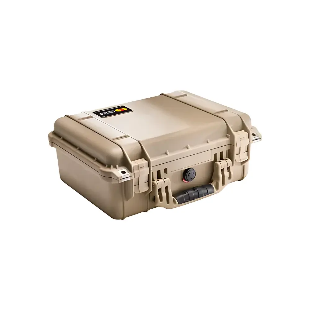
- Transport-optimized mechanical configuration: Main unit and HV tank are separable into sub-900 kg components compliant with standard freight pallet dimensions and crane-handling protocols; no special transport permits required within EU Class N1/N2 vehicle limits.
Sample Compatibility & Compliance
The HVA200 is validated for use with single- and three-core shielded cables having copper or aluminum conductors and extruded polymer insulation (XLPE, EPR, HEPR). It supports testing per ASTM D1169, IEC 60502-2 (for cables up to 30 kV), IEC 60840 (up to 150 kV), and IEEE 400.2 Annex B for VLF withstand criteria. All HV connections conform to IEC 61466-1 for live-line accessories. The system’s control logic and data logging architecture support audit-ready compliance with GLP and GMP environments—full timestamped event logs, user-access-level authentication, and tamper-evident report generation meet baseline requirements for regulatory submissions under ISO/IEC 17025-accredited laboratories.
Software & Data Management
The embedded Windows-based control interface (HVA Control Suite v4.x) provides real-time oscillographic visualization of voltage, current, and phase angle—with configurable trigger thresholds for automatic pass/fail evaluation against user-defined limits. Test data—including time-domain waveforms, harmonic spectra, and trended tan δ vs. voltage curves—are exportable via USB 2.0 or galvanically isolated optical fiber link (IEC 61850-3 compliant) to secure network servers. Reports comply with EN 61000-4-30 Class A for power quality traceability and include digital signatures per RFC 3161 timestamps. Audit trail functionality records all operator actions, parameter changes, and calibration events with immutable hashing—supporting FDA 21 CFR Part 11 electronic record requirements when deployed in regulated utility QA/QC workflows.
Applications
- Commissioning verification of newly installed underground transmission circuits (e.g., 66 kV–145 kV XLPE cables) prior to energization.
- Periodic diagnostic assessment of aged cable networks in urban distribution grids, including identification of water tree degradation through VLF-tan δ profiling.
- Sheath fault location using VLF-induced current injection and TDR-based impedance mapping—compatible with standard A-frame and clamp-on current sensors.
- Research-grade investigation of space charge accumulation dynamics in HVDC cable insulation under combined VLF-DC stress sequences.
- Third-party type testing and certification services conducted by national metrology institutes (NMIs) and independent high-voltage laboratories accredited to ISO/IEC 17025.
FAQ
What standards does the HVA200 comply with for VLF withstand testing?
It conforms to IEEE 400.2-2013, IEC 60502-2 Ed. 2.0, and CIGRÉ Technical Brochure 495 for test voltage magnitude, duration, and waveform tolerances.
Can the HVA200 perform simultaneous VLF withstand and partial discharge measurement?
Yes—when equipped with the optional PD module, it delivers synchronized 200 kV VLF stress and calibrated PD acquisition (0.5–20 pC sensitivity) per IEC 60270.
Is remote operation supported?
Local control is primary; however, Ethernet-over-fiber extension enables supervised remote monitoring and emergency shutdown via authenticated web interface—no direct internet exposure.
Does the system require periodic recalibration?
Voltage and current transducers are factory-calibrated to ±1.0% accuracy; annual verification against NIST-traceable HV dividers is recommended per ISO/IEC 17025 Clause 6.5.
What maintenance is required during field deployment?
No scheduled maintenance beyond visual inspection of HV terminations, grounding integrity checks, and humidity sensor validation—no oil, gas, or consumable components are used.