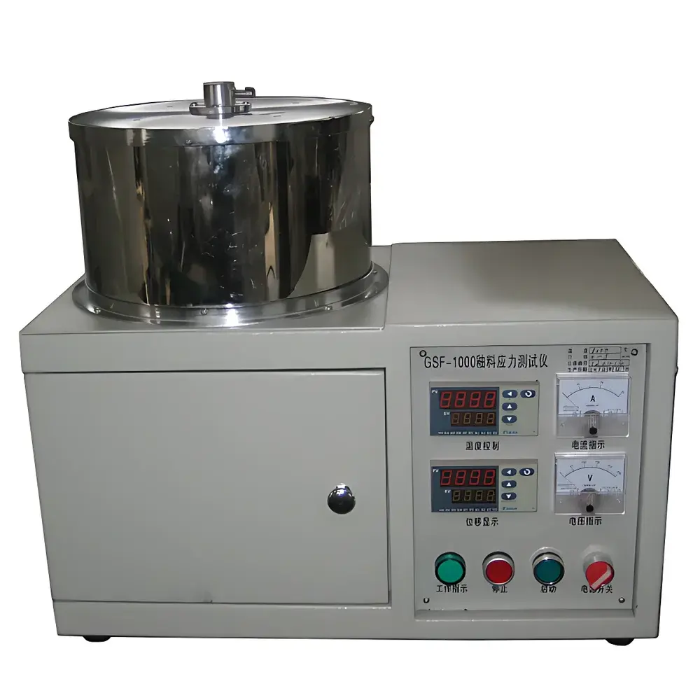
Ceramic Glaze Stress Analyzer GSF
| Key | Temperature Range: 1000 °C / 1400 °C / 1600 °C selectable |
|---|---|
| Heating/Cooling Rate | 0.01–20 K/min (programmable) |
| Displacement Measurement | LVDT differential inductive transducer |
| Max. Deflection Range | 5000 µm |
| Sample Dimensions | 260 mm (L) × ~12 mm (W) × ~6 mm (T) |
| glazed zone | ~80 mm central segment |
| Sample Holder | Metallic spiral clamping fixture |
| Atmosphere | Ambient air (static) or user-specified gas |
| Heating Power | ≥3 kW |
| Supply Voltage | 220 V or 380 V AC |
Overview
The GSF Ceramic Glaze Stress Analyzer is an engineered thermal-mechanical testing system designed to quantify residual and transient stresses developed during the firing cycle of ceramic glazes. It operates on the principle of controlled thermal bending—based on the well-established glaze stress bar method (ASTM C725, ISO 10545-13)—where a rectangular ceramic bar, partially glazed on its upper surface, is subjected to precisely regulated heating and cooling while its axial deflection is monitored in situ. Differential thermal expansion between the ceramic body and the molten or viscous glaze layer induces measurable curvature. By tracking the direction (concave up/down), magnitude, and temperature dependence of this bending, the instrument enables quantitative determination of compressive and tensile stress evolution across the critical vitrification and annealing ranges (typically 500–1200 °C). This provides direct insight into interfacial compatibility, thermal expansion mismatch (Δα), and the onset of stress relaxation mechanisms—key parameters governing glaze fit, crazing resistance, and long-term structural integrity.
Key Features
- Triple-range high-temperature furnace with selectable maximum operating temperatures (1000 °C, 1400 °C, or 1600 °C), enabling analysis across conventional stoneware, porcelain, and advanced technical ceramics;
- Precision programmable thermal control delivering ramp rates from 0.01 to 20 K/min with ±0.5 K stability over the full range;
- High-resolution LVDT-based displacement sensing system with 5000 µm full-scale range and sub-micron repeatability, calibrated for thermal drift compensation;
- Dedicated metallic spiral clamping fixture ensuring consistent, non-slipping sample fixation and minimizing parasitic mechanical constraints;
- Modular atmosphere capability: standard operation in static ambient air; optional inert or reducing gas purging ports for controlled-atmosphere studies;
- Robust power architecture with ≥3 kW heating capacity and dual-voltage compatibility (220 V / 380 V AC) for global laboratory integration.
Sample Compatibility & Compliance
The GSF analyzer accommodates standardized test bars measuring 260 mm in length, approximately 12 mm wide, and 6 mm thick, with a defined 80 mm glazed central zone. This geometry aligns with international reference protocols for glaze stress evaluation. The system supports both traditional oxide-based glazes and modern low-expansion frit systems, as well as experimental coatings on metallized substrates (e.g., enamel-on-metal research). Data acquisition and reporting conform to GLP-compliant documentation practices. While the base software does not natively implement FDA 21 CFR Part 11 electronic signature functionality, raw measurement files (.csv, .txt) are fully exportable for downstream audit-ready analysis in validated third-party platforms. The methodology referenced herein is traceable to ASTM C725 (“Standard Test Method for Determining Residual Stresses in Glazes”) and ISO 10545-13 (“Ceramic tiles — Part 13: Determination of glaze crazing resistance”).
Software & Data Management
The GSF control and analysis suite runs on Windows 7/XP SP2 and features a deterministic real-time acquisition engine synchronized with thermal profiling. The interface provides guided workflow navigation—including automated zero-point calibration at glaze softening temperature (defined as the inflection point in first derivative of curvature vs. temperature), peak stress identification, and endpoint detection. All raw deflection vs. temperature/time datasets are logged with timestamp, thermocouple ID, and environmental metadata. Post-acquisition tools include numerical differentiation (first and second order), baseline correction, comparative overlay of multiple runs, and export of annotated graphs in vector (EMF) or raster (PNG) formats. Software logs maintain full audit trails of operator actions, parameter changes, and calibration events—supporting internal quality review processes. Data files are structured for seamless import into MATLAB®, Python (NumPy/Pandas), or statistical analysis packages.
Applications
- Optimization of glaze-body thermal expansion matching to prevent crazing, shivering, or delamination;
- Development and qualification of low-thermal-expansion glazes for high-performance tableware and sanitaryware;
- Failure analysis of fired ceramic components exhibiting post-firing distortion or microcracking;
- Thermal history simulation for kiln schedule validation and energy-efficient firing profile design;
- Research into interfacial reaction layers formed between glaze and substrate during heat treatment;
- Comparative assessment of frit composition effects on stress development kinetics and relaxation behavior.
FAQ
What temperature accuracy and uniformity can be expected within the furnace chamber?
The furnace achieves ±1.5 °C temperature accuracy (traceable to NIST-certified thermocouples) and ±3 °C axial uniformity over the 80 mm active sample zone under steady-state conditions.
Is the LVDT sensor calibrated for thermal drift during extended high-temperature runs?
Yes—the system incorporates real-time cold-junction compensation and periodic auto-zero routines triggered at user-defined intervals or temperature plateaus to mitigate thermal drift artifacts.
Can the software generate reports compliant with ISO/IEC 17025 requirements?
While the native report generator supports customizable templates and digital signatures, formal ISO/IEC 17025 compliance requires integration with a laboratory information management system (LIMS) that manages instrument calibration records, personnel training logs, and uncertainty budgets—functions outside the scope of the embedded software.
What maintenance is required for the clamping mechanism after repeated thermal cycling?
The spiral clamp assembly is constructed from Inconel 718 and requires only periodic visual inspection for deformation; no lubrication or recalibration is needed due to its passive, spring-loaded mechanical design.
Are sample holders available for non-standard geometries (e.g., curved or irregular substrates)?
Custom fixtures—including low-profile holders for thin tiles or segmented supports for multi-zone glaze evaluation—can be fabricated upon request, subject to mechanical feasibility review and lead-time confirmation.
")


