Desatel LPMM Series Ultra-Thin MIMO LTE/CBRS Dedicated Antenna
| Brand | Panorama |
|---|---|
| Origin | Guangdong, China |
| Manufacturer Type | Authorized Distributor |
| Regional Category | Domestic (China) |
| Model | LPMM Series |
| Pricing | Available Upon Request |
| IP Rating | IP66 |
| Mounting | Panel-Mount (Conductive or Non-Conductive Surfaces) |
| Frequency Bands | 3.4–3.8 GHz & 4.9–6.0 GHz |
| MIMO Configuration | 4×4 |
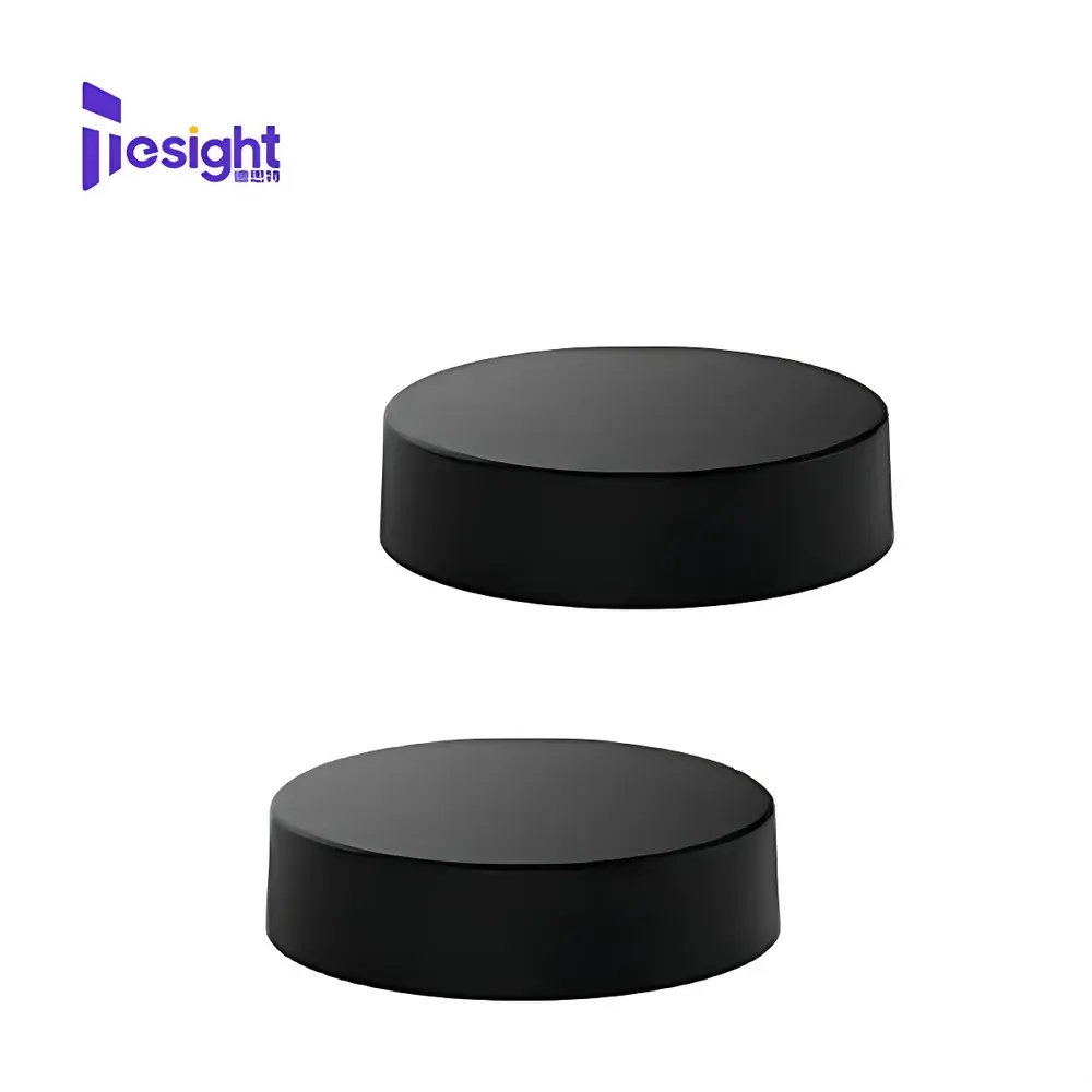
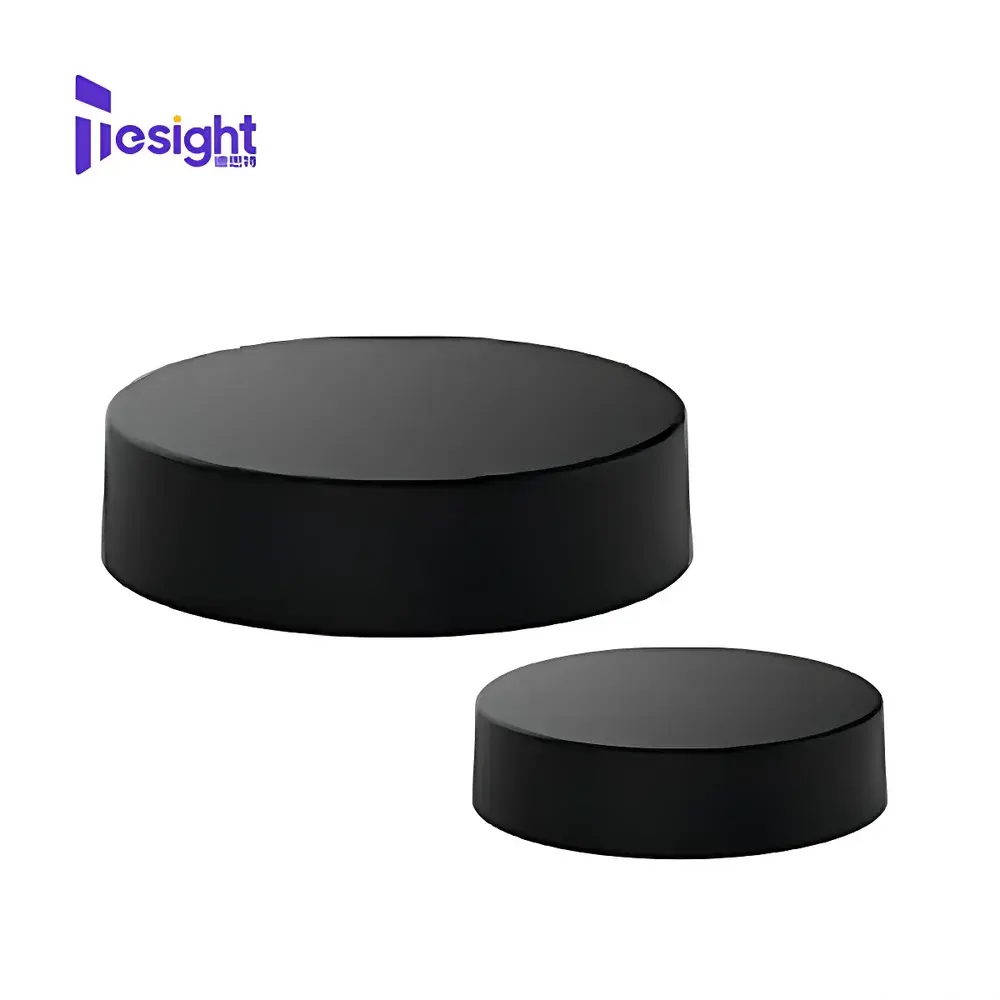
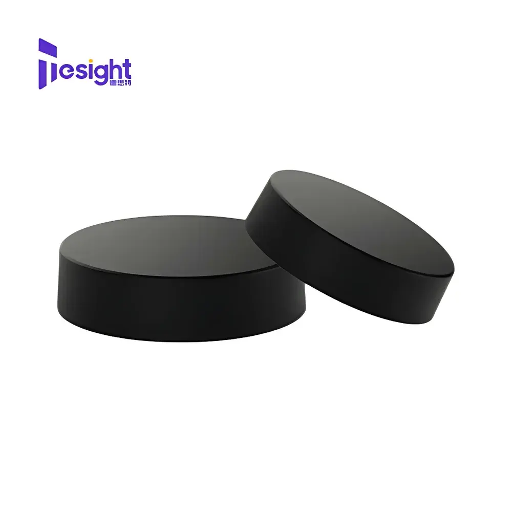
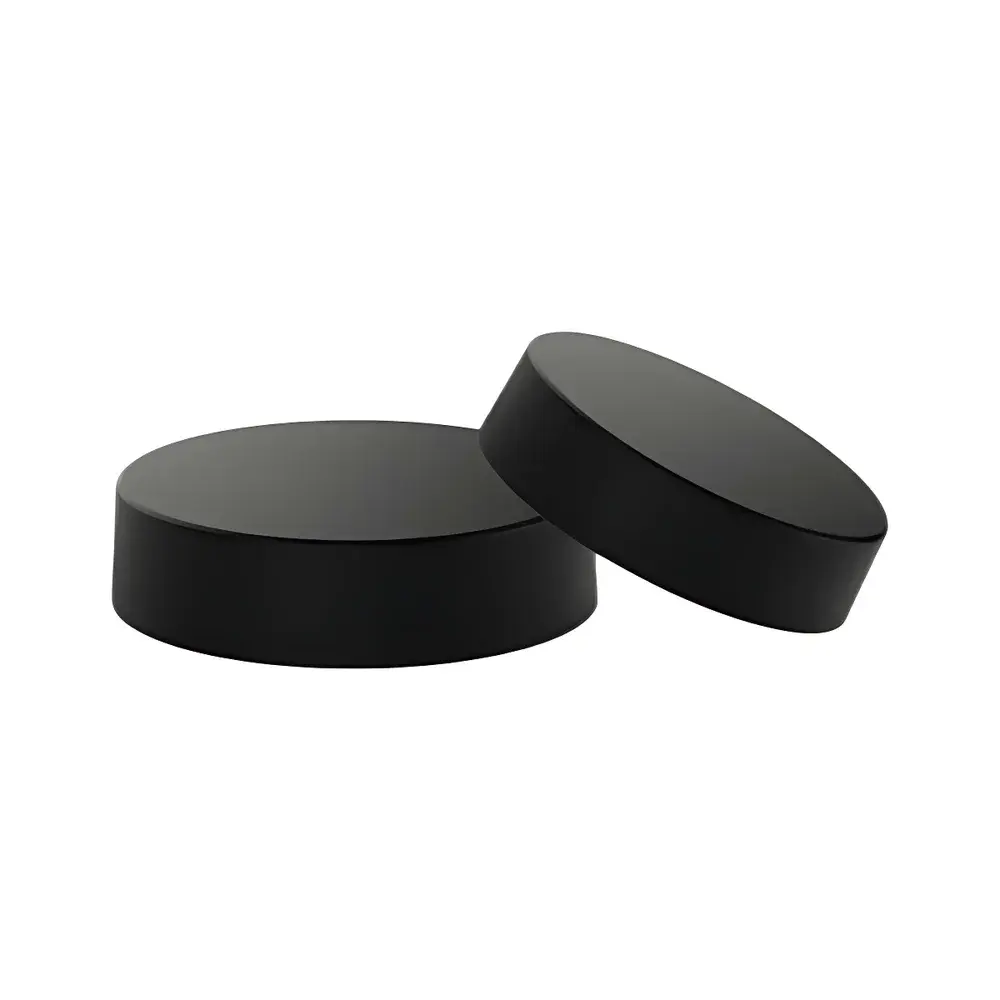
| Form Factor | Ultra-Thin, Compact Enclosure |
| Integrated Cable | RG174 |
| Compliance | RoHS, FCC Part 15 Subpart B (as applicable to host system), CE RED Directive (when integrated into compliant end equipment) |
Overview
The Desatel LPMM Series Ultra-Thin MIMO LTE/CBRS Dedicated Antenna is an engineered RF front-end solution designed for high-efficiency wireless connectivity in licensed and shared-spectrum bands. Based on proven aperture-coupled patch and planar inverted-F antenna (PIFA) architectures, the LPMM series operates across two critical regulatory bands: the Citizens Broadband Radio Service (CBRS) band (3.55–3.7 GHz), the extended 3.4–3.8 GHz LTE-TDD band widely deployed in private 4G/5G networks, and the 4.9–6.0 GHz unlicensed/LTE-U spectrum used in industrial private LTE deployments. Its 4×4 Multiple-Input Multiple-Output (MIMO) configuration enables spatial multiplexing, diversity gain, and improved link reliability—essential for mission-critical IoT infrastructure where consistent throughput and low latency are non-negotiable. The antenna’s ultra-thin profile (<8 mm total height) and panel-mount form factor allow seamless integration into space-constrained enclosures such as smart meter housings, kiosk chassis, and ruggedized edge gateways—without compromising radiated performance or requiring ground-plane extensions.
Key Features
- Ultra-compact mechanical design: Total thickness ≤ 8 mm; footprint optimized for embedded integration in industrial-grade enclosures.
- Dual-band operation: Simultaneous support for 3.4–3.8 GHz (LTE/CBRS) and 4.9–6.0 GHz (Private LTE, Wi-Fi 6E coexistence) with ≥15 dB inter-element isolation across both bands.
- 4×4 MIMO architecture: Four independently matched radiating elements arranged to minimize envelope correlation coefficient (ECC < 0.3) and maximize diversity gain per IEC 62774:2015 guidelines.
- IP66-rated enclosure: Fully sealed housing with UV-stabilized polymer housing and stainless-steel mounting hardware, validated per IEC 60529 for continuous outdoor deployment in temperatures from −40 °C to +70 °C.
- Integrated RG174 low-loss coaxial cable (1.5 m standard length): Pre-terminated with SMA male connectors; phase-matched within ±5° across operating bands to preserve MIMO channel coherence.
- Universal panel-mount compatibility: Supports flush mounting on conductive (metal) or non-conductive (plastic, fiberglass) substrates without detuning—no ground plane modification required.
Sample Compatibility & Compliance
The LPMM antenna is intended for integration into certified end-user equipment operating under FCC Part 15 Subpart B (unintentional radiator), FCC Part 24 (CBRS), ETSI EN 301 893 (5 GHz band), and ETSI EN 300 328 (2.4/5 GHz wideband). While the antenna itself is not a standalone certified transmitter, it complies with RoHS 2011/65/EU and REACH SVHC requirements. When integrated into systems subject to FDA 21 CFR Part 11 or IEC 62304 (for medical-grade telemetry), the antenna’s passive design introduces no software-controlled parameters and requires no firmware validation. It supports GLP/GMP-aligned test documentation workflows when used in metrology-grade field trials—full VSWR, gain, and pattern data available in NIST-traceable calibration reports upon request.
Software & Data Management
As a passive RF component, the LPMM antenna does not incorporate embedded firmware, microcontrollers, or digital interfaces. All performance characterization—including return loss (S11), isolation (S21/S31/etc.), peak gain, and radiation efficiency—is provided in industry-standard .s1p through .s4p touchstone files for use in Keysight PathWave ADS, CST Studio Suite, and ANSYS HFSS simulation environments. Measurement data is traceable to calibrated vector network analyzer (VNA) systems (Rohde & Schwarz ZNB/ZND series) operated in accordance with ISO/IEC 17025-accredited laboratory procedures. For production line testing, Desatel provides reference measurement fixtures and repeatability protocols compatible with automated RF test stations supporting SCPI command sets.
Applications
- Smart utility infrastructure: AMI (Advanced Metering Infrastructure) endpoints requiring robust CBRS-based backhaul in rural and suburban distribution grids.
- Industrial IoT gateways: Fixed wireless access nodes deployed in manufacturing plants, ports, and logistics hubs operating private LTE networks at 3.5 GHz or 5 GHz.
- Self-service retail systems: Vending machines, interactive kiosks, and digital signage platforms requiring reliable multi-carrier LTE fallback and low-profile RF integration.
- Public safety broadband terminals: Ruggedized mobile data terminals complying with FirstNet Band 48 (700 MHz) supplemental uplink coordination—where LPMM serves as secondary diversity antenna alongside primary low-band elements.
- Autonomous asset tracking: Telematics modules embedded in containerized freight units leveraging CBRS spectrum for real-time location reporting with sub-100 ms latency.
FAQ
Is the LPMM antenna certified for direct connection to FCC-certified base stations?
No—it is a component-level antenna intended for integration into end-equipment certified under FCC Part 22/24/15. System-level certification remains the responsibility of the OEM.
Can the RG174 cable be customized in length or connector type?
Yes—custom cable assemblies (including RP-SMA, N-type, or U.FL variants) and lengths up to 5 m are available under Desatel’s OEM service program with minimum order quantities.
Does the antenna support beamforming or active electronic steering?
No—it is a passive, fixed-pattern antenna. Beamforming functionality must be implemented at the transceiver level using baseband processing and precoding algorithms.
What is the typical impedance match bandwidth at VSWR ≤ 2.0?
Measured bandwidth exceeds 200 MHz per band: 3.48–3.68 GHz and 5.12–5.32 GHz, with center-frequency return loss better than −12 dB.
Are mechanical downtilt or azimuth adjustment options available?
Standard units feature fixed orientation; tilt-adjustable brackets and rotatable mounting kits are offered as optional accessories (Part No. LPMM-MB-KIT).


