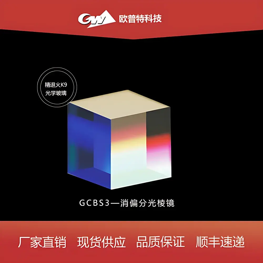
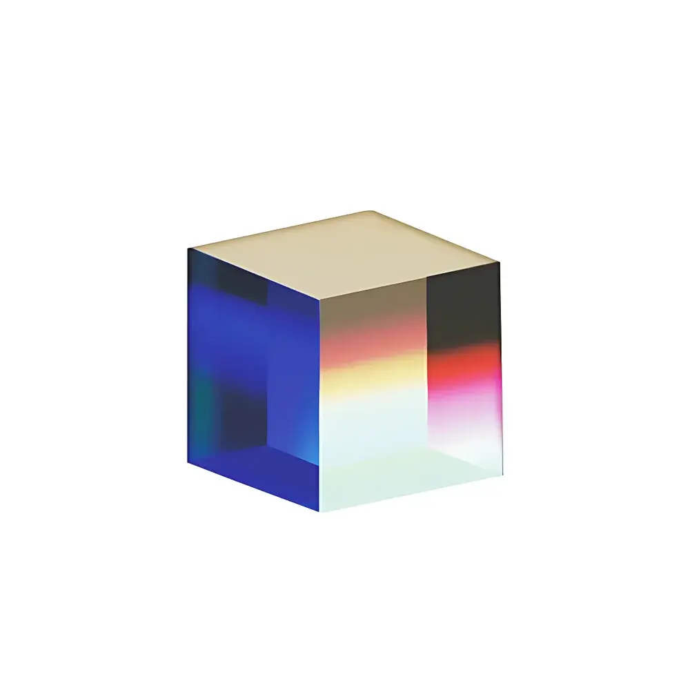
GCBS3 De-Polarizing Beam Splitter Cube
| Origin | Beijing |
|---|---|
| Manufacturer Type | Distributor |
| Origin Category | Domestic |
| Model | GCBS3 |
| Price Range | USD 72–143 |
| Component Category | Optical Element |
| Cube Side Lengths | 5.0, 10.0, 12.5, 15.0, 20.0, 25.4, 50.0 mm |
| Splitting Ratios (R/T) | 10/90, 30/70, 50/50, 70/30, 90/10 |
| Spectral Ranges | VIS (400–700 nm), NIR (700–1100 nm), SWIR (1100–1600 nm) |
| Mounting | Uncoated or AR-coated faces available per custom specification |
| Surface Flatness | λ/10 typical |
| Wavefront Distortion | < λ/8 over clear aperture |
| Material | UV-Fused Silica or BK7 (application-dependent) |
Overview
The GCBS3 De-Polarizing Beam Splitter Cube is a precision optical component engineered for stable, polarization-insensitive beam division in interferometric, imaging, and metrology systems. Unlike conventional plate-type beam splitters—whose asymmetric optical paths induce beam displacement, ghost reflections, and polarization-dependent phase shifts—the GCBS3 employs a cemented cube architecture with a dielectric thin-film coating deposited on the hypotenuse interface of two optically contacted prisms. This geometry ensures identical optical path lengths for both reflected and transmitted beams at 45° incidence, eliminating lateral beam shift, spatial walk-off, and polarization-induced intensity modulation. Its de-polarizing design maintains consistent R/T ratios across all input polarization states (linear, circular, unpolarized), making it suitable for applications where polarization fidelity cannot be assumed or controlled upstream.
Key Features
- Optical path equality: Identical propagation distances for reflected and transmitted beams ensure zero beam displacement and eliminate ghost image formation.
- Polarization independence: Engineered coating stack delivers stable splitting ratios regardless of incident polarization state—critical for broadband or unpolarized light sources.
- Multiple spectral variants: Available in three standardized wavelength bands—VIS (400–700 nm), NIR (700–1100 nm), and SWIR (1100–1600 nm)—with optimized coating performance per band.
- Configurable splitting ratios: Standard options include 10R/90T, 30R/70T, 50R/50T, 70R/30T, and 90R/10T to support diverse signal routing requirements (e.g., reference arm attenuation, power monitoring, or dual-path interferometry).
- High dimensional accuracy: Cube side lengths range from 5.0 mm to 50.0 mm, with tight tolerances (±0.1 mm) and parallelism < 10 arcsec, enabling direct integration into OEM optical mounts and kinematic platforms.
- Substrate flexibility: Constructed from UV-fused silica for deep-UV stability and low thermal expansion, or BK7 for cost-sensitive visible-range applications—both with surface flatness ≤ λ/10 and wavefront distortion < λ/8 over clear aperture.
Sample Compatibility & Compliance
The GCBS3 is compatible with collimated and moderately convergent beams (f-number ≥ f/4). It meets ISO 10110–7 surface quality specifications (scratch-dig 10–5) and complies with RoHS Directive 2011/65/EU. While not certified to specific IEC or MIL-STD standards as a standalone component, its material selection, coating adhesion (per ISO 21254–1), and environmental stability (operating temperature: –20 °C to +70 °C; humidity: ≤ 85% RH non-condensing) support integration into systems requiring GLP/GMP-aligned optical assemblies. No laser-induced damage threshold (LIDT) data is provided for pulsed operation; continuous-wave use up to 5 W/cm² is validated for VIS/NIR variants under clean-room handling conditions.
Software & Data Management
As a passive optical component, the GCBS3 requires no firmware, drivers, or software integration. However, its performance parameters—including spectral reflectance/transmittance curves, angular sensitivity profiles, and polarization extinction ratio (PER > 30 dB across specified bands)—are documented in NIST-traceable calibration reports supplied with each batch. These reports conform to ISO/IEC 17025:2017 requirements for testing laboratories and are archived for traceability in accordance with FDA 21 CFR Part 11–compliant document control systems when deployed in regulated analytical instrumentation.
Applications
- Michelson and Mach–Zehnder interferometers requiring path-length-matched arms and polarization-agnostic splitting.
- Multi-spectral imaging systems integrating VIS, NIR, and SWIR channels via dichroic beam routing.
- Laser cavity output coupling where minimal wavefront distortion and polarization neutrality are essential.
- Optical coherence tomography (OCT) sample/reference arm dividers operating across 800–1300 nm windows.
- Automated inspection systems using structured illumination or triangulation, where beam alignment stability reduces recalibration frequency.
- Quantum optics experiments involving entangled photon pairs, where polarization-independent splitting preserves Bell-state fidelity.
FAQ
What does “de-polarizing” mean in this context?
It indicates that the beam splitter’s reflectance and transmittance values remain invariant across all input polarization states—unlike polarizing cubes, which exhibit strong dependence on s- and p-polarization components.
Can the GCBS3 be used at angles other than 45°?
While optimized for 45° incidence, angular deviation up to ±3° maintains R/T ratio stability within ±2% for 50/50 variants; larger deviations require ray-tracing validation per application.
Is anti-reflection coating standard on outer faces?
No—AR coating is optional and specified per order (e.g., VIS-AR: R < 0.25% per surface @ 550 nm; NIR-AR: R < 0.3% @ 1064 nm).
How is spectral performance verified?
Each production lot undergoes spectrophotometric characterization using a calibrated double-beam UV-VIS-NIR spectrometer (PerkinElmer Lambda 1050+), with data reported in CSV and PDF formats compliant with ASTM E275–22.
Are custom splitting ratios or substrate materials available?
Yes—custom R/T ratios (e.g., 40/60, 60/40) and substrate alternatives (CaF₂, SF10) are available under OEM agreements with minimum order quantities and extended lead times.