Impact Collision Test System – Heavy-Duty Electromechanical Shock and Bump Tester
| Key | Brand: OEM / Third-Party Industrial Supplier |
|---|---|
| Origin | Imported (Non-US/EU Designated Origin) |
| Manufacturer Type | Authorized Distributor |
| Quoted Price | USD 16,800 (FOB Origin, Excluding VAT, Freight & Installation) |
Overview
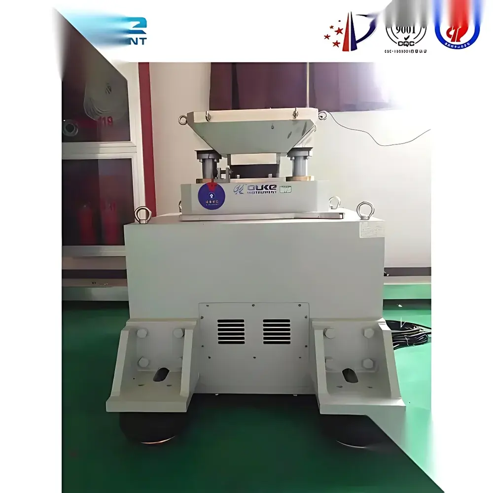
The Impact Collision Test System is an electromechanical shock and bump testing platform engineered for precise simulation of mechanical shock environments in accordance with IEC 60068-2-27 (Shock), IEC 60068-2-29 (Bump), MIL-STD-810H Method 516.8, and ISO 16750-3. It operates on the principle of controlled free-fall impact: a vertically actuated impact mass is elevated by a DC motor-driven reduction gearbox and roller-lift mechanism, then released to strike a calibrated elastomeric buffer pad. The resulting acceleration pulse—primarily half-sine by default—is governed by Newtonian dynamics, where peak acceleration (gn) is derived from velocity change (Δv) and pulse duration (tp): apeak ≈ Δv / tp. With gn referenced to 10 m/s² for engineering simplification, the system delivers repeatable, traceable shock profiles suitable for qualification testing of electronic enclosures, automotive ECUs, aerospace avionics housings, and industrial control modules.
Key Features
- Electromechanical lift-and-drop architecture with brushless DC motor and precision planetary reducer—eliminates hydraulic fluid maintenance and ensures long-term positional repeatability.
- Real-time closed-loop acceleration control via high-bandwidth piezoelectric accelerometers mounted directly on the test table, enabling dynamic compensation for mass loading and buffer compression variance.
- Optical position feedback system (photoelectric encoder + linear scale) guarantees sub-millimeter lift height accuracy—critical for consistent Δv generation across test cycles.
- Dual-mode operation: configurable for both shock (single transient pulse) and bump (repetitive low-energy impacts), supporting up to 60 cycles per minute at nominal severity levels.
- Modular buffer interface accommodates interchangeable pads of varying durometer (Shore A 30–90) and thickness (10–50 mm), enabling empirical tuning of pulse width (0.5–30 ms) and waveform shape.
- Rigid welded steel frame with reinforced top plate ensures ≤ ±5% spatial uniformity of peak acceleration across the full 400 × 400 mm test surface (per ISO 16750-3 Annex B).
- Expandable waveform library includes user-defined trapezoidal and post-peak sawtooth pulses—programmable via onboard controller or external PC interface.
Sample Compatibility & Compliance
The system accommodates DUTs weighing up to 50 kg with mounting footprints ≤ 350 × 350 mm. Fixturing uses M6–M8 tapped holes on the table surface with optional T-slot rails. All test protocols comply with GLP-aligned documentation requirements: each test run logs timestamp, lift height, measured peak g, pulse width, velocity change, and waveform signature. Calibration certificates (traceable to NIST or PTB equivalents) are provided with initial delivery. The system meets CE machinery directive (2006/42/EC) safety requirements and supports audit-ready records for ISO 9001:2015, IATF 16949, and DO-160G Section 8 compliance verification.
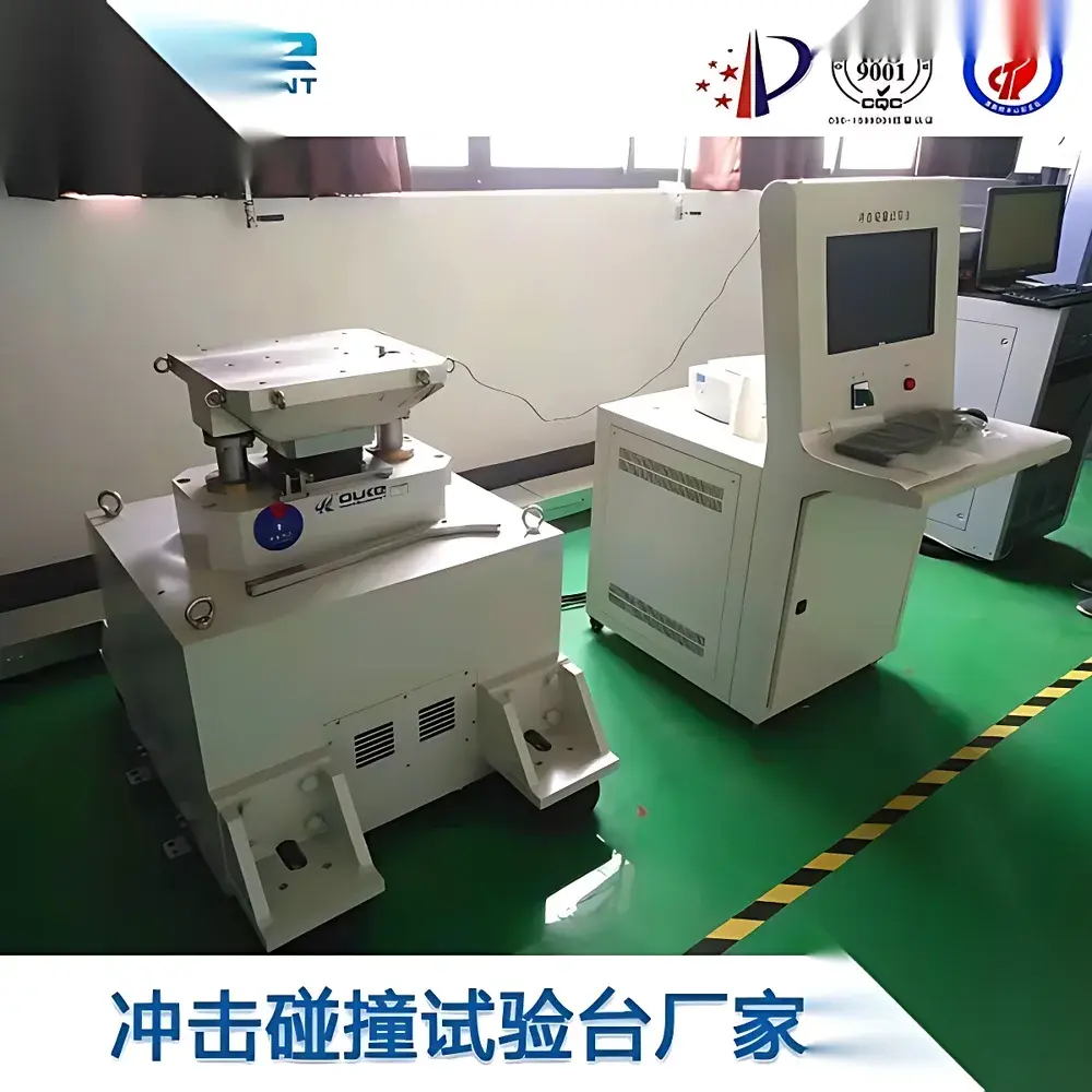
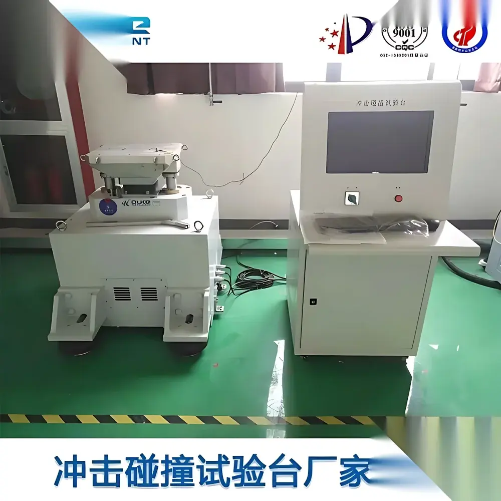
Software & Data Management
Control and analysis are performed via Windows-based application with dual operating modes: manual setup (for quick qualification checks) and automated test sequence (for multi-step shock profiles). Raw accelerometer data is sampled at 1 MHz with 16-bit resolution and stored in IEEE-compliant .tdms format. Software includes built-in FFT analysis, pulse parameter extraction (apeak, tp, vchange), pass/fail thresholding against user-defined limits, and PDF report generation with digital signature support. Audit trail functionality satisfies FDA 21 CFR Part 11 requirements for electronic records and signatures when deployed in regulated manufacturing environments.
Applications
- Functional validation of PCB-level robustness under transportation shock (e.g., drop during logistics).
- Design verification of latch mechanisms, display mounts, and connector retention systems.
- Pre-compliance screening for automotive component suppliers targeting OEM specifications (e.g., VW 80000, GM W3177).
- Reliability assessment of battery management systems (BMS) and power electronics subjected to road-induced bump loads.
- Educational use in mechanical vibration labs for hands-on demonstration of shock response spectra and SDOF system behavior.
FAQ
What is the standard calibration interval for this system?
Annual calibration is recommended; factory-certified recalibration services include accelerometer sensitivity verification, lift height linearity check, and pulse shape fidelity assessment against reference transducers.
Can the system be integrated into an existing test automation framework?
Yes—it supports TCP/IP and Modbus RTU communication protocols, enabling seamless integration with LabVIEW, Python-based test orchestrators, or MES platforms via OPC UA gateway.
Is operator training included with purchase?
A two-day on-site commissioning and operator training session is provided, covering safety procedures, test method setup, data export workflows, and basic troubleshooting.
Does the system meet MIL-STD-810H Method 516.8 Category 4 requirements?
When configured with appropriate buffer stacks and verified using certified reference accelerometers, it achieves Category 4 severity levels (e.g., 400 g, 2 ms half-sine) with ≤ ±10% amplitude tolerance per test cycle.


