Impact Shock Test System
| Key | Table Surface Dimensions: 200 × 200 mm |
|---|---|
| Maximum Payload | 10 kg |
| Pulse Duration Range | 0.2–100 ms (programmable, auto-controlled) |
| Peak Acceleration Range | 50–9999 m/s² (programmable, auto-controlled) |
| Pulse Waveform | Half-sine (compliant with IEC 60068-2-27, GB/T 2423.5, GJB 150.18A, GJB 360B, JJG 497) |
| Shock Direction | Vertical |
| Dual-Impact Prevention | Hydraulic-friction braking system |
| Height Control | Digital preset + hydraulic lifting |
| Sampling Rate | 200 kHz |
| Signal Conditioning | Analog filtering + 160 dB/oct digital anti-aliasing filter |
| Repetition Rate | 0–100 shocks/min (±1% accuracy) |
| Power Supply | AC 380 V ±10%, 50 Hz, 3 kVA |
| System Mass | 2800 kg |
| Overall Dimensions | 750 × 2600 × 1000 mm |
| Software Platform | Windows XP-based, DAO data engine, automated Word report generation, real-time display of lift height, peak acceleration, pulse width, and Δv |
Overview
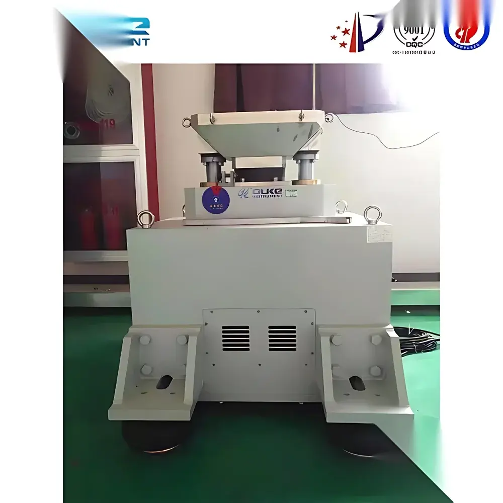
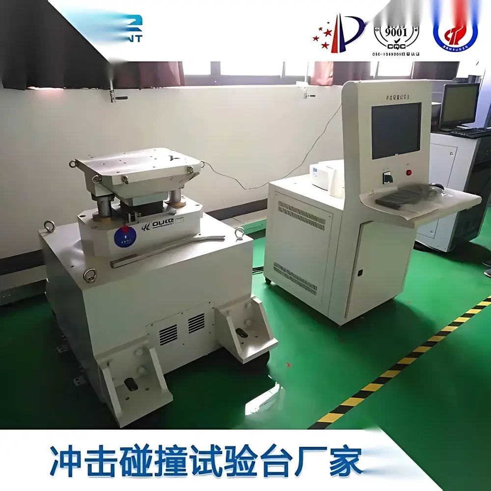
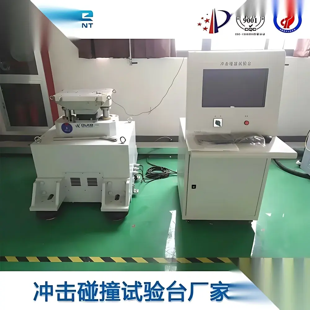
The Impact Shock Test System is a vertically oriented electro-hydraulic shock test table engineered for precise, repeatable mechanical shock simulation in compliance with international environmental testing standards. It operates on the principle of controlled free-fall impact: a test specimen mounted on a rigid platform is elevated to a programmable height and released, generating a calibrated half-sine acceleration pulse upon impact with a resilient base. This method replicates transient mechanical stresses encountered during transportation, handling, or operational deployment—enabling rigorous evaluation of structural integrity, solder joint reliability, sensor robustness, and packaging performance. The system’s core architecture integrates high-stiffness mechanical framing, closed-loop hydraulic height control, and real-time digital signal acquisition to ensure metrological traceability and experimental reproducibility across qualification and acceptance testing protocols.
Key Features
- Programmable half-sine shock pulse generation with adjustable peak acceleration (50–9999 m/s²) and pulse duration (0.2–100 ms), both set via digital interface and executed with ±1% measurement accuracy.
- Vertical shock orientation with 200 × 200 mm rigid aluminum test surface, rated for payloads up to 10 kg—optimized for small-to-medium electronic assemblies, PCBs, MEMS devices, and miniature enclosures.
- Hydraulic-friction dual-impact prevention mechanism eliminates rebound effects, ensuring single-event pulse fidelity critical for ISO/IEC 17025-compliant calibration workflows.
- Digital height presetting and hydraulic lifting enable rapid, repeatable setup without manual adjustment—reducing operator-induced variability between test runs.
- Integrated 200 kHz sampling data acquisition subsystem featuring analog anti-aliasing filters and a 160 dB/oct digital anti-aliasing filter to preserve waveform integrity and support accurate pulse parameter extraction (tp, amax, Δv).
- Robust structural design: 2800 kg total mass and reinforced steel frame minimize energy loss and resonance coupling, maintaining pulse shape fidelity across the full operational range.
Sample Compatibility & Compliance
This system accommodates specimens conforming to standard mounting configurations per IEC 60068-2-27 (Shock), GB/T 2423.5 (Chinese national standard), GJB 150.18A (MIL-STD-810H equivalent for defense equipment), GJB 360B (electronic component testing), and JJG 497 (calibration verification of shock machines). Pulse waveform tolerance is configurable within defined limits: front-edge 0.4D to rear-edge 0.1D or 1.1D (where D = pulse duration), enabling alignment with user-defined test profiles. The system supports automatic pulse width tracking and real-time deviation monitoring relative to target tolerances—essential for GLP/GMP audit readiness and third-party certification reporting.
Software & Data Management
The embedded Windows XP-based control and analysis software utilizes Microsoft DAO as its native data access object engine, ensuring stable relational database handling for multi-parameter time-series records. It provides synchronized visualization of lift height, real-time acceleration waveform, calculated velocity change (Δv), and derived metrics including shock response spectrum (SRS) post-processing. All raw and processed data are timestamped and stored with full metadata (operator ID, test standard reference, environmental conditions if interfaced). Automated report generation exports compliant documentation—including summary tables, annotated waveforms, statistical summaries (mean, SD, CPK), and pass/fail determinations—directly into editable Microsoft Word format. Audit trail functionality meets basic requirements for FDA 21 CFR Part 11–aligned environments when deployed with appropriate IT governance controls.
Applications
- Qualification testing of avionics modules subjected to launch vibration and stage separation shock loads.
- Reliability screening of automotive ECUs, airbag controllers, and ADAS sensors under road-induced shock exposure.
- Package validation for medical device shipments per ISTA 3A and ASTM D4169 protocols.
- Failure mode analysis of solder interconnects using JEDEC JESD22-B110-referenced shock profiles.
- Calibration verification of piezoelectric accelerometers and charge amplifiers per ISO 16063-21.
- Research-grade dynamic response characterization of composite laminates and additively manufactured lattice structures.
FAQ
What shock standards does this system natively support?
The system is configured to generate pulses compliant with IEC 60068-2-27, GB/T 2423.5, GJB 150.18A, GJB 360B, and JJG 497. Custom pulse definitions can be loaded via software configuration files.
Is the system suitable for production-line incoming inspection?
Yes—it supports programmable test sequences with pass/fail logic, automated reporting, and batch logging, making it deployable in QC/QA environments where throughput and traceability are prioritized.
Can the software interface with external environmental chambers or data loggers?
The system provides RS-232 and Ethernet ports for TTL-level trigger synchronization and ASCII command protocol integration; custom OPC UA or Modbus TCP gateways may be implemented via third-party middleware.
What maintenance intervals are recommended?
Hydraulic fluid and filter replacement every 12 months or 500 operating hours; annual calibration verification of accelerometer channels and height encoder against NIST-traceable references is advised.
Is technical support available outside mainland China?
Yes—remote diagnostics, firmware updates, and application engineering consultation are provided globally through authorized service partners with certified shock test specialists.


