Inframet IPAS Series Image Intensifier Power Supply Test System
| Brand | Inframet |
|---|---|
| Origin | Poland |
| Model | IPAS-A / IPAS-B / IPAS-C |
| Application | Static & Dynamic Electrical Characterization and Photometric Performance Evaluation of Gen II Image Intensifier Tubes |
| Compliance | Designed for R&D, QA, and calibration labs supporting night vision device manufacturing and military optics certification protocols |
Overview
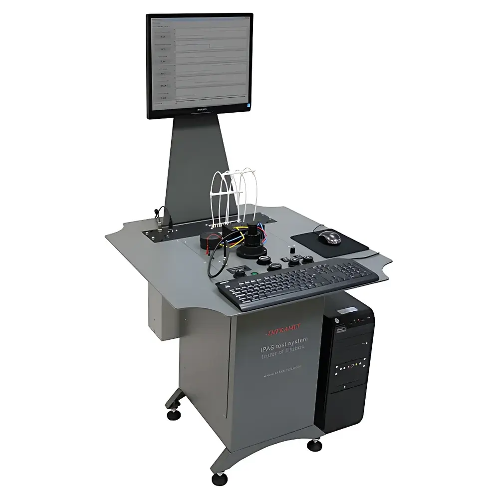
The Inframet IPAS Series Image Intensifier Power Supply Test System is a precision-engineered platform for comprehensive electrical and photometric characterization of Generation II (Gen II) image intensifier tubes. Built upon a modular architecture, the system enables traceable, repeatable measurement of inter-electrode voltages (e.g., photocathode-to-MCP, MCP-to-phosphor), current draw under static and pulsed illumination, and photometric output—including brightness gain, saturation behavior, and photocathode luminous sensitivity (lm/W). Its core measurement principle integrates synchronized high-voltage DC/DC monitoring with calibrated optical excitation and photometric detection, enabling correlation between input light stimulus (spectrally matched to S-20 or S-25 response curves), power supply regulation fidelity, and output phosphor luminance. The system is deployed in optics R&D laboratories, defense-grade component qualification facilities, and ISO/IEC 17025-accredited calibration centers where strict adherence to MIL-STD-3009, STANAG 4680, and NATO AEP-97 test methodologies is required.
Key Features
- Modular, scalable design supporting three operational configurations: IPAS-A (static DC characterization only), IPAS-B (static + dynamic pulse-response analysis up to 10 kHz), and IPAS-C (adds MI2 microscope integration for MTF and resolution mapping per ISO 12233 and MIL-STD-150A)
- High-stability programmable light source with adjustable intensity (0.1–1000 cd/m²), spectral output (peaked at 550 nm ±10 nm), and pulse width (1 µs–100 ms), calibrated against NIST-traceable standards
- Simultaneous multi-channel voltage/current acquisition across all tube electrodes (photocathode, MCP input/output, anode, phosphor) using isolated HV probes (±5 kV, 0.1% accuracy) and low-noise current shunts (1 nA–10 mA range)
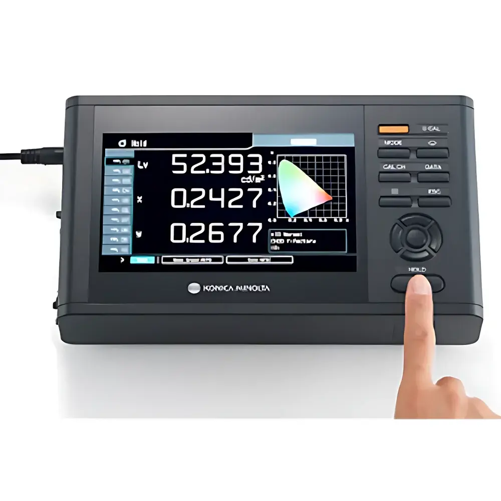
- LP4 calibrated brightness probe with f/1.2 aperture, 0.1 cd/m² minimum detectable luminance, and spectral response aligned to CIE 1931 V(λ) curve
- VCM (Voltage & Current Monitoring) software suite providing real-time oscilloscope-style waveform capture, parameter trend logging, and automated compliance reporting against user-defined pass/fail thresholds
- Fully isolated signal paths and EMI-hardened cabling to ensure measurement integrity in high-voltage, low-current environments typical of microchannel plate operation
Sample Compatibility & Compliance
The IPAS system accommodates both encapsulated and bare Gen II image intensifier tubes via interchangeable mechanical adapters (standardized to DIN 40129 and MIL-DTL-38999 interfaces). It supports common tube geometries including 18 mm, 25 mm, and 40 mm active diameters, with configurable electrode access for direct probe attachment. All electrical measurements comply with IEC 61000-4-5 (surge immunity) and IEC 61326-1 (EMC for laboratory equipment). Software-generated reports include audit trails, timestamped metadata, and instrument calibration certificates—fully compatible with GLP/GMP documentation requirements and FDA 21 CFR Part 11 electronic record controls when deployed on validated Windows OS platforms.
Software & Data Management
IPAS control software provides a unified GUI for hardware configuration, stimulus scheduling, and real-time data visualization. VCM software performs synchronized acquisition of up to 8 analog channels at 1 MS/s sampling rate, with built-in FFT analysis, rise/fall time calculation, and transient overshoot quantification. Data export supports CSV, HDF5, and MATLAB .mat formats; raw waveforms retain full bit-depth resolution (16-bit ADC). The system includes automated report generation templates aligned with MIL-HDBK-338B failure mode analysis and ISO/IEC 17025 uncertainty budgeting frameworks. Calibration history, operator ID, environmental conditions (temperature/humidity), and equipment IDs are embedded in every dataset.
Applications
- Qualification testing of high-voltage power supplies used in night vision goggle (NVG) assemblies
- Root-cause analysis of gain instability, halo formation, or gating delay in image intensifier modules
- Photocathode aging studies under accelerated life testing (ALT) protocols
- Verification of MCP voltage divider network stability and leakage current under thermal cycling
- Supporting DO-160 Section 22 (lightning-induced transient) and MIL-STD-810H Method 516.7 (shock/vibration) test readiness
- Calibration reference setup for secondary standards laboratories servicing defense contractors
FAQ
What distinguishes IPAS-B from IPAS-A?
IPAS-B adds synchronized optical pulsing capability and high-speed transient acquisition (≥100 kS/s per channel), enabling analysis of power supply response latency, MCP recovery time, and phosphor persistence decay profiles.
Is the LP4 brightness probe NIST-traceably calibrated?
Yes—each LP4 probe ships with a certificate of calibration valid for 12 months, referencing NIST SRM 2242 and performed in accordance with ISO/IEC 17025 accredited procedures.
Can the system interface with third-party DAQ or automation platforms?
Yes—VCM software exposes a documented TCP/IP API and LabVIEW-compatible DLLs for integration into automated test stands and MES-controlled production lines.
Does IPAS support Gen III or filmless MCP tubes?
While optimized for Gen II, the IPAS-B and IPAS-C configurations can be adapted for Gen III evaluation via custom electrode fixtures and extended voltage range options (up to ±15 kV); contact Inframet Application Engineering for configuration validation.
What maintenance intervals are recommended for long-term metrological reliability?
Annual recalibration of HV probes and LP4 sensor is recommended; quarterly verification of light source spectral output and intensity stability using onboard reference photodiodes is advised per ISO/IEC 17025 Clause 7.7.