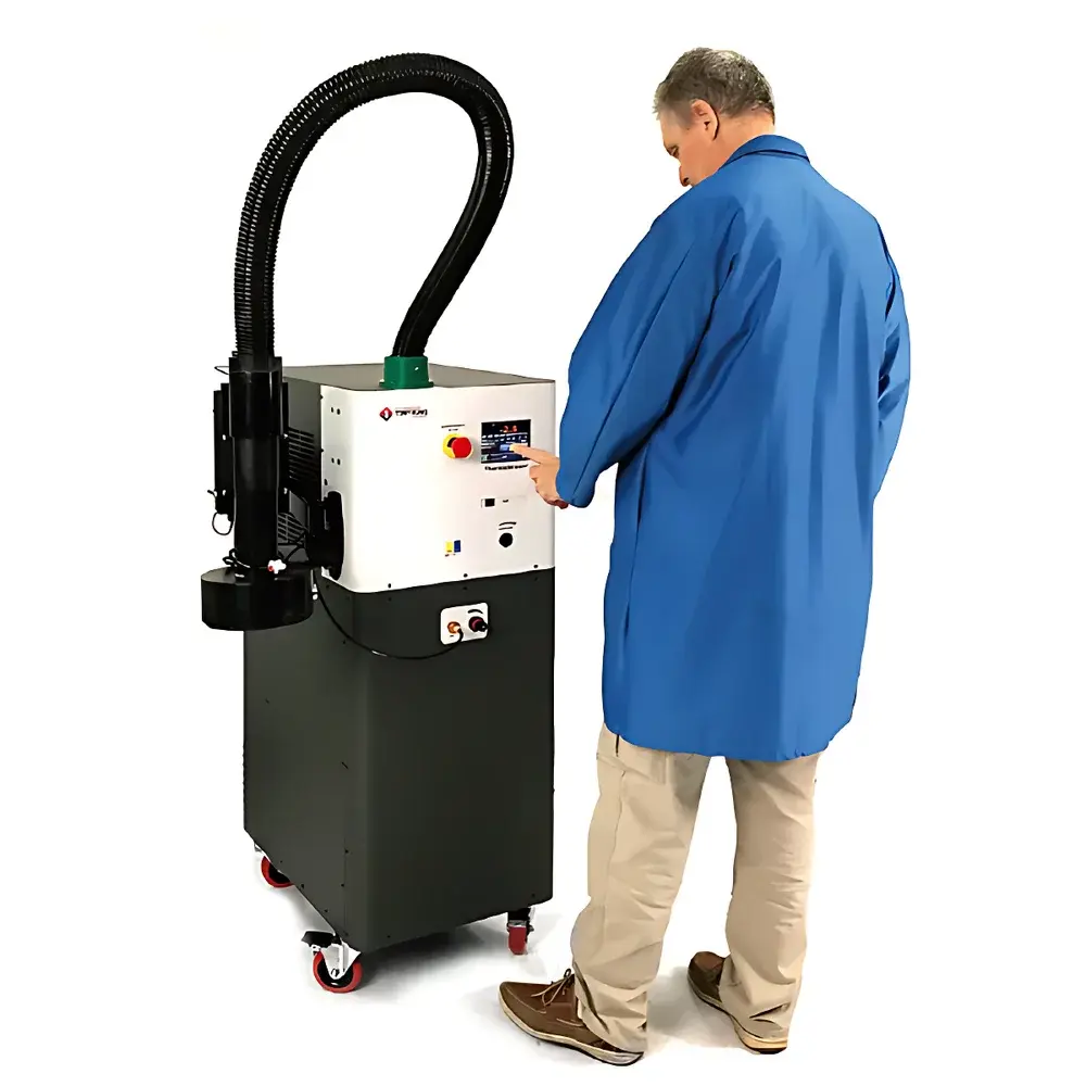
inTEST Temptronic ATS-545-M ThermoStream Thermal Shock Test System for Transceiver Temperature Cycling
| Brand | inTEST-Temptronic |
|---|---|
| Origin | USA |
| Model | ATS-545-M |
| Temperature Range | –80°C to +225°C |
| Cooling/Heating Method | Compressed Dry Air with Integrated Refrigeration & Resistive Heating |
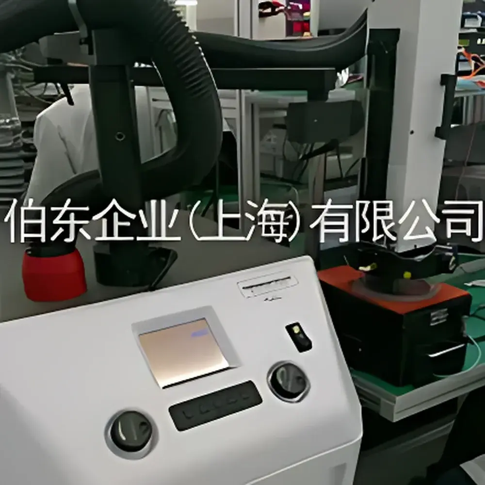
| Control Interface | Rotary Knob Panel with Real-Time Sensor Feedback |
| Over-Temperature Protection | Factory-Set at +230°C, User-Configurable Limit |
| Form Factor | Mobile Benchtop Unit Compatible with Robotic Handler Integration |
| Compliance | Designed for GLP/GMP-aligned test environments |
Overview
The inTEST Temptronic ATS-545-M ThermoStream Thermal Shock Test System is a high-speed, localized temperature cycling platform engineered specifically for component-level thermal qualification of optical transceivers and other high-density photonic devices. Unlike conventional environmental chambers that subject entire PCB assemblies or trays to uniform thermal profiles, the ATS-545-M employs directed, laminar flow of temperature-controlled dry air to isolate and thermally stress individual transceivers—enabling precise, rapid, and non-invasive thermal cycling without thermal crosstalk to adjacent components. Its operational principle leverages a closed-loop air management architecture: compressed instrument-grade air is first cooled via an integrated refrigeration module, then routed through a precision resistive heating head before delivery through a thermally optimized nozzle and heat shroud directly into a custom DUT chamber. This design achieves typical ramp rates exceeding 100°C/min between –80°C and +225°C—significantly surpassing the performance envelope of forced-air ovens or walk-in thermal shock chambers.
Key Features
- Mobile benchtop form factor with casters and ergonomic height adjustment—designed for integration into automated test cells with robotic handlers.
- DUT Mode operation enables single-device thermal profiling: real-time feedback from embedded thermocouples or RTD sensors within the test cavity drives closed-loop temperature regulation.
- Rotary knob control panel provides tactile, deterministic parameter setting—ideal for production floor use where GUI-based interfaces may introduce latency or calibration drift.
- Integrated over-temperature protection system with dual-stage monitoring: hardware-limited cutoff at +230°C (factory default), plus user-definable upper/lower thermal thresholds with automatic shutdown and event logging.
- Refrigeration and heating subsystems are decoupled and independently monitored—ensuring stable setpoint hold during extended dwell periods at extreme temperatures.
- No consumables required: operates solely on clean, oil-free compressed air (dew point ≤ –40°C) and standard AC power—eliminating liquid nitrogen, cryogenic fluids, or hazardous coolants.
Sample Compatibility & Compliance
The ATS-545-M accommodates industry-standard transceiver packages including SFP+, QSFP28, OSFP, and COBO-compliant modules, as well as bare-die photonics mounted on custom carriers. Its modular nozzle and heat shroud system allows mechanical adaptation to varying DUT footprints and thermal mass profiles. From a regulatory standpoint, the system supports traceable thermal validation workflows compliant with Telcordia GR-468-CORE (Section 4.4.1.1, Temperature Cycling), IEC 61215 (for photonic subassemblies), and ASTM F2079 (Standard Practice for Thermal Cycling of Semiconductor Devices). While not a Class I medical device, its firmware architecture includes audit-trail-capable event logging—facilitating alignment with FDA 21 CFR Part 11 requirements when deployed in GMP-regulated manufacturing or reliability labs.
Software & Data Management
The ATS-545-M operates in standalone mode via its front-panel interface; however, it features RS-232 and optional Ethernet (Modbus TCP) communication ports for external SCADA or MES integration. All thermal events—including start/stop timestamps, setpoint deviations, sensor readings, and safety interlock triggers—are timestamped and stored in non-volatile memory for post-test analysis. When paired with inTEST’s optional ThermoStream Control Software Suite (v4.2+), users can define multi-step thermal profiles (e.g., –40°C × 15 min → ramp @ 120°C/min → +85°C × 10 min → ramp → cycle × 500), export CSV-formatted thermal logs, and generate PDF reports with embedded calibration certificates. Data integrity safeguards include cyclic redundancy checks (CRC-16) on all serial transmissions and write-protected configuration archives.
Applications
- Component-level thermal screening of pluggable optical transceivers prior to final assembly and burn-in.
- Failure mode analysis (FMA) of solder joint fatigue, epoxy delamination, and thermo-mechanical stress-induced wavelength drift in DFB/VCSEL lasers.
- Qualification testing per GR-468-CORE Clause 4.4.1.1 (Temperature Cycling) and GR-1209-CORE (Thermal Shock).
- Process validation of reflow profiles for co-packaged optics and silicon photonics integration.
- Accelerated life testing (ALT) of active optical cables (AOCs) and electro-optic modulators under controlled thermal transients.
- Research-grade thermal boundary characterization of heterogeneous packaging materials (e.g., silicon carbide substrates, LTCC carriers, microchannel heatsinks).
FAQ
What is the minimum DUT size supported by the ATS-545-M?
The system supports DUTs as small as 5 mm × 5 mm using optional micro-nozzle adapters; standard configuration accommodates modules up to 150 mm × 100 mm.
Does the ATS-545-M require liquid nitrogen or external chillers?
No—it uses only compressed dry air and internal vapor-compression refrigeration; no cryogens or auxiliary cooling infrastructure are needed.
Can the unit be validated for ISO/IEC 17025 accredited laboratories?
Yes—its temperature uniformity (±0.8°C across 25 mm DUT zone), stability (±0.3°C over 30 min dwell), and traceable NIST-traceable calibration path support accreditation documentation.
Is remote monitoring possible without proprietary software?
Yes—via Modbus TCP register mapping, third-party LabVIEW, Python (PyModbus), or Ignition SCADA systems can read real-time temperature, status flags, and alarm states.
How is airflow calibrated and verified during routine maintenance?
inTEST provides a certified airflow verification kit (P/N TS-AFV-KIT) including a NIST-traceable hot-wire anemometer and nozzle-specific flow maps; annual recalibration is recommended per ISO 17025 Clause 6.5.


