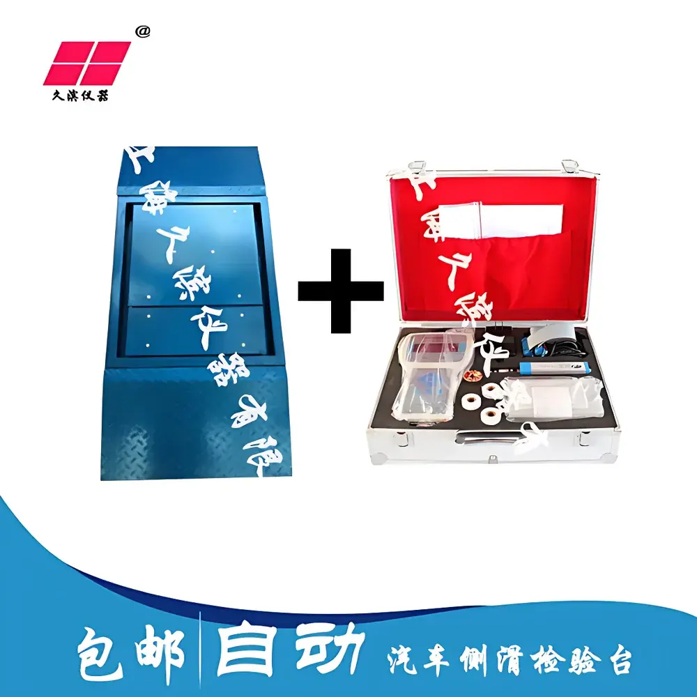
JB-10 Single-Plate Automotive Side-Slip Test Bench by Jiubin Instruments
| Brand | Jiubin Instruments |
|---|---|
| Model | JB-10 |
| Type | Single-Plate Side-Slip Test Bench for Motor Vehicle Wheel Alignment Verification |
| Max. Axle Load | 10 t |
| Measurement Range | ±10 m/km |
| Indication Error | ≤ ±0.2 m/km |
| Zero Offset Error | ±0.2 m/km |
| Sliding Plate Dimensions | 500 mm × 700 mm |
| Overall Bench Dimensions (L×W×H) | 800 mm × 900 mm × 100 mm |
| Approach Ramp Dimensions | 800 mm × 500 mm |
| Compliance Standard | JT/T 507–2004 |
Overview
The JB-10 Single-Plate Automotive Side-Slip Test Bench is an electromechanical measurement system engineered for regulatory and maintenance-level verification of front-wheel alignment geometry in passenger vehicles, light-duty trucks, and commercial vans. It quantifies the net lateral displacement—expressed in millimeters per kilometer (m/km)—generated when a vehicle traverses the bench at low speed (typically 3–5 km/h) under free-rolling, no-steering-input conditions. This displacement arises from the vector summation of camber-induced lateral force and toe-induced scrub effect, providing a composite indicator of wheel alignment integrity. Unlike dual-plate systems that isolate left/right contributions, the single-plate configuration measures total side-slip as a system-level parameter, making it suitable for routine safety inspection stations, vehicle inspection centers (VICs), and workshop-based preventive maintenance protocols where throughput and mechanical robustness are prioritized.
Key Features
- High-stability sliding plate assembly with precision-ground stainless steel bearing surfaces and low-friction linear guides, ensuring repeatable mechanical response over >500,000 test cycles
- Integrated strain-gauge-based displacement transducer with analog signal conditioning circuitry, delivering linearity within ±0.1% FS across the full ±10 m/km range
- Digital signal processing module incorporating hardware filtering (10 Hz low-pass), programmable gain amplification, and 16-bit ADC resolution for noise-immune data acquisition
- Modular structural design compliant with JT/T 507–2004 mechanical interface specifications, including standardized approach ramp geometry and mounting anchor points
- DC 12 V control architecture for intrinsic electrical safety—eliminating risk of mains-voltage exposure during operator interaction or service intervention
- Locking pin mechanism for secure immobilization of the sliding plate during non-operational periods or calibration verification procedures
Sample Compatibility & Compliance
The JB-10 accommodates vehicles with axle loads up to 10 metric tons, covering Class M1 (passenger cars), M2/M3 (buses), and N1/N2 (light/medium goods vehicles) as defined in UN Regulation No. 13-H and GB 7258–2017. Its 500 mm × 700 mm active sliding surface supports standard tire widths ranging from 145 mm to 285 mm. The bench is certified to meet the metrological and mechanical requirements of China’s national transportation industry standard JT/T 507–2004, which specifies performance criteria for indication accuracy, zero stability, repeatability, temperature drift tolerance (±0.02 m/km/°C), and mechanical rigidity under static load. While not inherently FDA- or ISO/IEC 17025-accredited, its traceable calibration methodology aligns with GLP-aligned workshop practices for periodic verification using certified gauge blocks and reference displacement simulators.
Software & Data Management
The JB-10 operates as a standalone analog-digital hybrid instrument with local LED display of real-time side-slip value (±X.X m/km). For integration into centralized inspection management systems, optional RS-232 or RS-485 serial output modules are available—supporting ASCII-based data streaming compatible with common automotive inspection software platforms (e.g., I-MI, AutoCheck Pro, and regional VIC middleware). All firmware implements timestamped internal logging of last calibration date, operator ID (via external keypad input), and pass/fail status relative to jurisdictional limits (e.g., ≤ ±5 m/km per GB 38900–2020). Audit trails comply with basic data integrity principles required under CNAS-CL01:2018 for non-accredited testing facilities.
Applications
- Routine safety inspections in authorized motor vehicle inspection stations (MVIS) operating under provincial transport authority mandates
- Pre-delivery alignment verification in OEM dealer service centers prior to customer handover
- Post-repair validation following suspension component replacement (control arms, tie rods, struts)
- Periodic fleet maintenance screening for municipal bus operators and logistics companies
- Technical training and certification assessments in vocational automotive schools accredited by MOE or MOT
FAQ
What is the maximum permissible axle load for the JB-10?
The JB-10 is rated for a maximum static axle load of 10,000 kg. Exceeding this limit may compromise mechanical integrity and invalidate measurement traceability.
Does the unit require periodic recalibration—and if so, how often?
Yes. Per JT/T 507–2004 Clause 6.4.2, calibration verification must be performed before each daily shift and after any impact event or mechanical adjustment. Full recalibration using certified displacement standards is recommended every 6 months or after 10,000 tests, whichever occurs first.
Can the JB-10 be used for vehicles with dual rear wheels or wide-base tires?
Yes—provided the combined tread width does not exceed 285 mm and the axle load remains within specification. Dual-wheel configurations must be tested one axle at a time, with the non-tested axle positioned fully off the sliding plate.
Is the device compatible with modern CAN-bus diagnostic systems?
No. The JB-10 is a dedicated mechanical-electrical transduction platform without native CAN interface. Integration with vehicle network diagnostics requires third-party gateway hardware and custom protocol mapping.
What environmental conditions are required for valid operation?
Ambient temperature: 5–40 °C; relative humidity: ≤85% RH non-condensing; floor flatness tolerance: ≤0.1 mm/m over the entire installation area; no standing water, oil residue, or structural vibration sources within 1 m of the bench footprint.

")