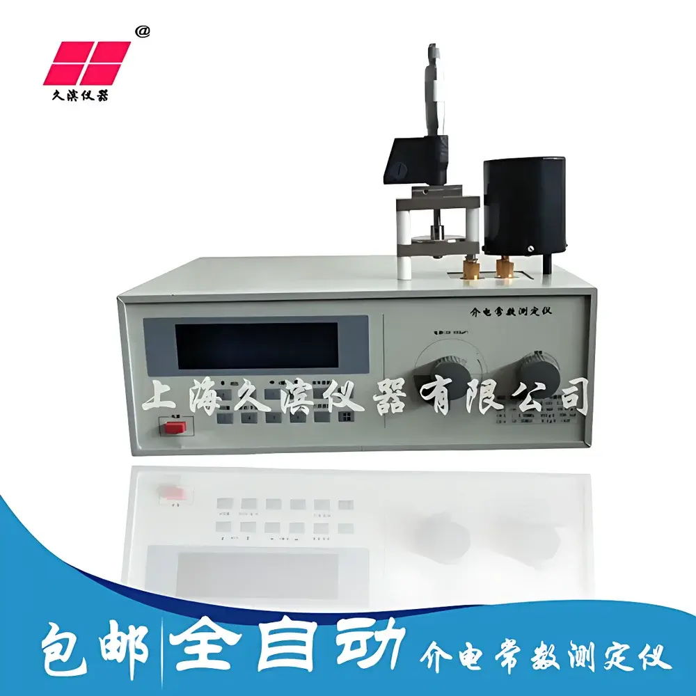
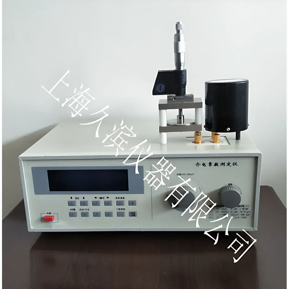
JB-A Dielectric Constant and Loss Tangent Analyzer by Jiubin Instruments
| Brand | Jiubin Instruments |
|---|---|
| Origin | Shanghai, China |
| Model | JB-A |
| Frequency Range | 10 kHz – 70 MHz |
| Main Capacitance Tuning Range | 30–500 pF |
| Capacitance Resolution | ±0.2 pF |
| Q Factor Range | 1–1000 (auto/manual range switching) |
| Q Measurement Accuracy | <5% |
| Q Resolution | 0.1 (4-digit display) |
| Capacitance Measurement Range | 1–460 pF |
| Loss Tangent (tan δ) Determination Method | Resonant Q-shift comparison using dual-variable capacitor system |
| Dielectric Constant (εᵣ) Calculation | Based on parallel-plate capacitance ratio with/without sample |
Overview
The JB-A Dielectric Constant and Loss Tangent Analyzer is a precision resonant-frequency impedance measurement system engineered for quantitative characterization of insulating solid materials. It operates on the principle of high-Q series resonance in a shielded LC oscillator circuit, where dielectric properties are derived from perturbations in resonant frequency and quality factor (Q) induced by sample insertion into a calibrated parallel-plate electrode assembly. Unlike broadband impedance analyzers or LCR meters operating at fixed frequencies, the JB-A employs direct digital synthesis (DDS) to sweep and lock onto the precise resonant frequency within 10 kHz–70 MHz—enabling high-sensitivity detection of minute changes in complex permittivity (ε* = ε′ − jε″). The instrument implements a dual-capacitor architecture: a main tuning capacitor (30–500 pF) establishes baseline resonance, while a high-resolution cylindrical variable capacitor (resolution: 0.0033 pF) serves as the null-detection transducer for Q and capacitance variation. This design conforms to classical ASTM D150 and IEC 60250 methodologies for measuring relative permittivity (εᵣ) and dissipation factor (tan δ) of rigid dielectrics under controlled environmental conditions.
Key Features
- DDS-based signal generation ensures stable, low-phase-noise oscillation across the full 10 kHz–70 MHz range, supporting material characterization at multiple standardized test frequencies (e.g., 1 MHz, 10 MHz, 50 MHz).
- Automatic compensation for residual inductance and lead inductance eliminates systematic error sources inherent in high-frequency RF measurements—critical for reproducible εᵣ and tan δ values below 10⁻⁴.
- Digital micro-adjustment readout provides direct, real-time capacitance display with ±0.2 pF accuracy and 4-digit Q resolution (0.1 step), eliminating parallax and interpolation errors common in analog scale systems.
- Four auto-ranging Q scales (30, 100, 300, 999) enable seamless transition between low-loss ceramics (tan δ < 10⁻⁴) and moderately lossy polymers (tan δ up to ~0.05), maintaining optimal signal-to-noise ratio throughout.
- Modular electrode interface supports standardized parallel-plate fixtures per ASTM D2520, with optional guarded electrodes available for surface resistivity correlation studies.
Sample Compatibility & Compliance
The JB-A analyzer is validated for use with rigid, non-porous solid dielectrics including oxide ceramics (Al₂O₃, TiO₂), glass substrates, mica sheets, thermoset laminates (FR-4), and injection-molded engineering plastics (PEEK, PTFE, polyimide). Sample thickness must be uniform (±2 µm) and surfaces polished to Ra < 0.1 µm to minimize air-gap capacitance uncertainty. Measurements comply with ISO 2577 (plastics), ASTM D150-22 (solid electrical insulating materials), and IEC 60250 (determination of permittivity and dielectric dissipation factor). The instrument’s Q-based calculation method satisfies GLP traceability requirements when paired with NIST-traceable calibration standards (e.g., air-dielectric reference capacitors certified to ±0.05 pF).
Software & Data Management
While the JB-A operates as a standalone benchtop instrument with front-panel digital readouts, it supports manual data logging via RS-232 interface (optional USB-to-serial adapter). Raw Q and capacitance values are exportable as CSV for post-processing in MATLAB, Python (SciPy), or Excel. For regulated environments, third-party LabVIEW drivers are available to integrate JB-A readings into automated test sequences compliant with FDA 21 CFR Part 11—supporting electronic signatures, audit trails, and data integrity controls required in GMP-compliant R&D labs.
Applications
- Quality control of ceramic capacitor dielectrics during sintering process development.
- Comparative evaluation of polymer matrix formulations for high-frequency PCB substrates.
- Research into ferroelectric phase transitions via temperature-dependent εᵣ and tan δ profiling (when coupled with environmental chamber).
- Validation of thin-film coating uniformity on semiconductor wafers using normalized capacitance deviation analysis.
- Educational laboratories demonstrating fundamental relationships between molecular polarization mechanisms and macroscopic dielectric response.
FAQ
What sample dimensions are recommended for accurate εᵣ measurement?
Standard specimens should be circular or square, 25–50 mm in diameter/side, with thickness between 0.5 mm and 5 mm. Electrode coverage must exceed 95% of the sample surface area to minimize fringing field error.
Does the JB-A support liquid or powder samples?
No—it is designed exclusively for solid, self-supporting dielectrics. Liquids require coaxial probe or waveguide-based systems; powders necessitate pelletization under controlled pressure and humidity prior to testing.
How is calibration performed?
Calibration uses air-gap capacitance as primary reference (εᵣ = 1.00054), followed by verification with certified low-loss quartz or fused silica standards. No user-accessible internal trimmers are provided; factory recalibration is recommended annually or after mechanical shock.
Is the instrument compatible with vacuum or elevated-temperature testing?
The base unit is rated for ambient operation (15–30 °C, RH < 70%). Integration with external environmental chambers requires custom electrode feedthroughs and is supported under engineering consultation—not covered under standard warranty.
What documentation is supplied for regulatory submissions?
Factory calibration certificate, ASTM/IEC compliance statement, and electrical safety report (GB 4793.1 / IEC 61010-1) are included. Full validation packages (IQ/OQ/PQ protocols) are available upon request for pharmaceutical or aerospace QA departments.
Related Products


