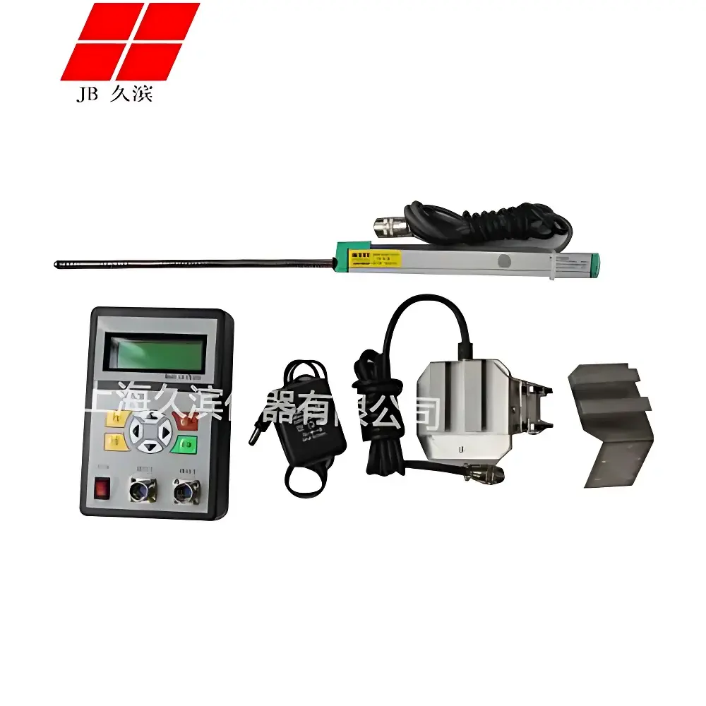
Jiubin JB-230 Pedal Travel and Force Tester
| Brand | Jiubin |
|---|---|
| Model | JB-230 |
| Measurement Principle | Dual-channel analog signal acquisition with Σ-Δ A/D conversion (12-bit) |
| Force Range | 0–1000 N |
| Travel Range | 0–150 mm |
| Force Resolution | 1 N |
| Travel Resolution | 1 mm |
| Accuracy | ±1% FS |
| Display | Dot-matrix LCD with Chinese character interface |
| Power Supply | 8.4 V Ni-Cd rechargeable battery pack |
| Communication | RS232 (9-pin D-sub, 9600 bps, 8N1, pin 2 RX, pin 3 TX, pin 5 GND) |
| Compliance | Designed for automotive brake/clutch pedal evaluation per ISO 13479, SAE J2865, and GB/T 26777–2011 |
Overview
The Jiubin JB-230 Pedal Travel and Force Tester is a dedicated dual-parameter instrumentation system engineered for quantitative evaluation of mechanical actuation characteristics in automotive pedal assemblies—specifically brake, clutch, and accelerator pedals. It operates on a microcontroller-based architecture centered on the MCS-51 family, integrating high-stability analog front-end circuitry with a 12-bit Σ-Δ analog-to-digital converter to ensure consistent digitization of force and displacement signals. Unlike generic load cells or linear potentiometers used in ad-hoc setups, the JB-230 employs synchronized sampling of two independent analog channels: one conditioned for strain-gauge-based force transduction, the other for precision linear displacement sensing via calibrated mechanical linkage or integrated LVDT-style feedback. Real-time acquisition enables concurrent logging of force (N) and travel (mm), with automatic peak-hold capture for both parameters—critical for regulatory compliance testing where maximum actuation force and full-travel displacement must be documented under standardized loading protocols.
Key Features
- Dual-sensor architecture supporting simultaneous measurement of pedal force and linear travel with time-aligned data stamps
- Embedded dot-matrix LCD display with native Chinese character support for on-device operation without external PC dependency
- On-board non-volatile memory for local storage of up to 99 test records, each retaining force-time and travel-time curves plus peak values
- Standard 9-pin RS232 serial interface compliant with EIA/TIA-232-F specifications; configurable for direct connection to laboratory PCs or industrial SCADA systems
- Rechargeable 8.4 V Ni-Cd battery pack providing ≥8 hours of continuous field operation; charging circuit includes overvoltage and thermal cutoff protection
- Modular mechanical interface with universal mounting brackets and interchangeable pedal adapters compatible with flat, curved, and offset pivot geometries
Sample Compatibility & Compliance
The JB-230 is validated for use across passenger vehicles (M1/M2), light commercial vehicles (N1), and low-speed electric platforms where pedal actuation metrics fall within its 0–1000 N / 0–150 mm operational envelope. Its mechanical coupling design accommodates OEM-standard pedal arm lengths (120–320 mm), pivot offsets (±25 mm), and surface contact diameters (15–45 mm). The instrument supports test execution per internationally recognized standards including ISO 13479:2012 (Brake system pedal force and travel requirements), SAE J2865 (Clutch pedal effort and travel test procedure), and China’s GB/T 26777–2011 (Motor vehicle brake pedal travel and force testing methods). While not certified to IEC 61000-4 electromagnetic immunity levels, its shielded signal paths and galvanically isolated analog stages meet basic EMC robustness for shop-floor deployment.
Software & Data Management
Raw data export is supported via ASCII-formatted RS232 transmission using fixed-field comma-delimited structure: timestamp, force_value_N, travel_value_mm, peak_force_N, peak_travel_mm, test_id. No proprietary software is bundled; however, the protocol is fully documented and interoperable with MATLAB, LabVIEW, Python (pySerial), and Excel-based post-processing workflows. For regulated environments, users may integrate the JB-230 into validated data acquisition systems that enforce 21 CFR Part 11-compliant audit trails—provided the host software implements electronic signatures, user access controls, and immutable record archiving. The device itself does not store operator credentials or maintain change logs, and thus functions as a data source rather than a standalone compliant system.
Applications
- Production line verification of pedal assembly consistency prior to vehicle roll-off
- Aftermarket brake system diagnostics—identifying excessive free play, hydraulic resistance anomalies, or master cylinder inefficiency through force-travel hysteresis analysis
- R&D validation of pedal ratio optimization and booster assist calibration
- Periodic maintenance checks in fleet service centers to detect wear-induced travel creep or force degradation
- Academic research on human-machine interface (HMI) ergonomics, including pedal stiffness perception thresholds and fatigue-related actuation drift
- Third-party certification testing labs performing type-approval submissions for new vehicle platforms
FAQ
Does the JB-230 support real-time graphing during measurement?
No—the built-in LCD displays numeric values only (current and peak force/travel); waveform visualization requires external data logging via RS232.
Can the device measure both brake and clutch pedals without hardware modification?
Yes—mechanical adaptability is achieved through interchangeable mounting fixtures; no recalibration is required when switching between pedal types.
Is calibration traceable to national metrology institutes?
The unit ships with a factory calibration certificate referencing internal reference standards; end-user traceable calibration requires periodic verification against NIST-traceable force and displacement standards.
What is the temperature operating range?
Specified for 0 °C to 40 °C ambient; extended-range operation beyond this is not characterized and may affect accuracy.
How is zero-point stability maintained during long-duration tests?
Auto-zero compensation is applied at power-on and manually triggered before each test sequence; thermal drift is mitigated by low-drift op-amp circuitry and matched sensor bridge configurations.
Related Products
 and Vehicle Classification System")