Metrolab HallinSight® 3D Hall Effect Magnetic Field Camera for Surface Magnetic Flux Distribution Mapping
| Brand | Auniontech |
|---|---|
| Origin | Shanghai, China |
| Manufacturer Type | Authorized Distributor |
| Regional Category | Domestic (China) |
| Model | HallinSight® 3D |
| Quotation | Upon Request |
Overview
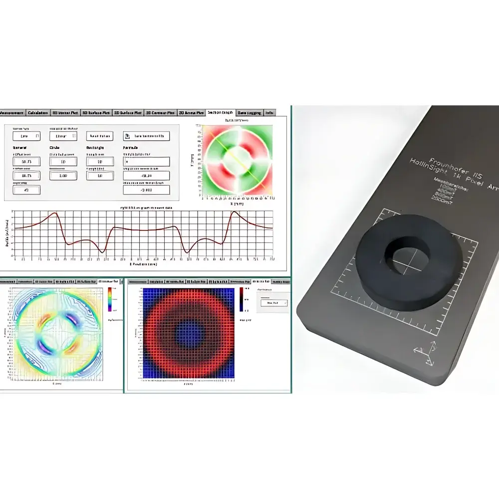
The Metrolab HallinSight® 3D Hall Effect Magnetic Field Camera is an advanced vector magnetic imaging system engineered for high-fidelity, real-time spatial mapping of surface magnetic flux density distributions. Developed in collaboration with Fraunhofer IIS (Institute for Integrated Circuits), this instrument implements a true three-axis Hall sensor array architecture to capture the full Bx, By, and Bz vector components simultaneously at each spatial node. Unlike conventional single-axis scanning probes or scalar magnetometers, HallinSight® delivers genuine 3D vector field data without mechanical reorientation—enabling quantitative characterization of static, quasi-static, and dynamic magnetic fields up to 250 Hz frame rate. Its core measurement principle relies on solid-state Hall effect physics, calibrated against traceable magnetic standards, ensuring metrological integrity across its four selectable ranges (±100 mT to ±2 T). The system is optimized for non-contact, non-destructive evaluation of permanent magnets, magnetic assemblies, electromagnetic devices, and functional materials—providing sub-millimeter spatial fidelity and microtesla-level resolution essential for R&D labs and industrial QA/QC environments.
Key Features
- True 3D vector magnetic field imaging: simultaneous acquisition of Bx, By, and Bz at every pixel without mechanical rotation or interpolation artifacts
- Spatial resolution down to 2.5 mm grid pitch, with lateral geometric accuracy < 50 µm and vertical accuracy < 10 µm
- Vector resolution of 4 µT per axis, supported by four auto-ranging modes: ±100 mT, ±400 mT, ±800 mT, and ±2 T
- Real-time acquisition rates up to 250 Hz (for 32×2 linear array), 100 Hz (16×16 planar), and 25 Hz (32×32 planar)
- Integrated temperature sensors for thermal drift compensation and long-term measurement stability
- Factory-performed full-system magnetic calibration traceable to national metrology institutes
- Magnetically neutral housing design minimizing perturbation of the measured field
- Multi-interface connectivity: USB 2.0 (bulk transfer mode) and ASCII-based serial protocol for seamless integration into automated test benches
Sample Compatibility & Compliance
The HallinSight® camera supports non-invasive characterization of flat, curved, or stepped magnetic surfaces—including sintered NdFeB, SmCo, ferrite, and AlNiCo magnets; magnetic encoders; motor stators/rotors; magnetic shielding components; and magnetized thin films. It complies with ISO/IEC 17025 requirements for calibration laboratories when used with documented uncertainty budgets. While not certified to specific regulatory standards (e.g., IEC 61000-4-8), its measurement traceability, documented linearity (<0.2% FS), orthogonality error (<0.1°), and repeatability (±0.5% over 8-hour operation) align with GLP-compliant magnetic testing workflows. All firmware and calibration files are version-controlled and timestamped—supporting audit readiness for internal quality systems.
Software & Data Management
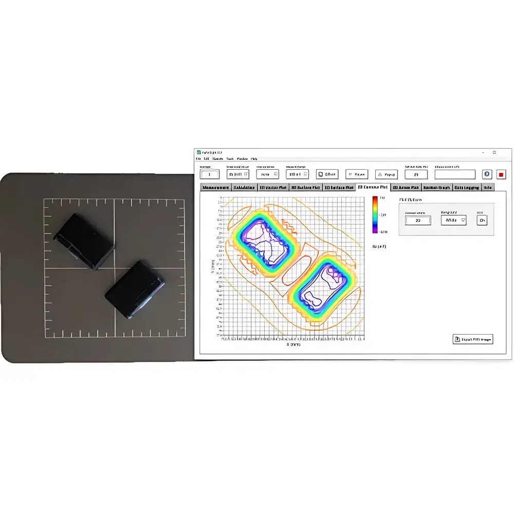
The included Windows-native HallinSight® Control & Analysis Suite provides real-time visualization of vector field magnitude, direction, divergence, and curl maps. Raw data exports in HDF5 and CSV formats preserve metadata (timestamp, sensor ID, temperature, range setting, calibration coefficients). The software supports batch processing, cross-sectional profile extraction, and field gradient computation. LabVIEW drivers (NI-VISA compliant) and Python API (via PySerial and NumPy) enable custom automation for inline inspection or closed-loop control applications. All data sessions include embedded audit trails: user login, parameter changes, calibration events, and export actions—facilitating compliance with FDA 21 CFR Part 11 where electronic records are required.
Applications
- Quality assurance in permanent magnet manufacturing: detection of magnetization non-uniformity, edge demagnetization, and domain misalignment
- Non-destructive evaluation (NDE) of magnetic materials: identification of subsurface cracks, voids, and inclusions via field distortion signatures
- Characterization of magnetic assemblies: air-gap field profiling in motors, actuators, and magnetic couplings
- Current mapping in conductive structures: visualization of eddy current paths and hidden fault currents (e.g., PV module interconnect failures)
- Dynamic field analysis: time-resolved imaging of pulsed magnetic fields in MRI shimming coils or particle accelerator beam diagnostics
- Multidimensional position sensing: reconstruction of 3D position/orientation from harmonic field patterns in magnetic tracking systems
FAQ
What is the smallest detectable field change the HallinSight® can resolve?
The system achieves a vector resolution of 4 µT per axis under optimal conditions (±100 mT range, low-noise environment, stabilized temperature).
Can HallinSight® measure fields inside enclosed assemblies?
No—it is designed for surface-field mapping only. Penetration depth is limited to the sensor-to-surface distance; no internal volumetric reconstruction is performed.
Is magnetic calibration performed on-site or at the factory?
Full-system calibration is conducted at the manufacturer’s metrology lab prior to shipment. Users may perform verification checks using reference Helmholtz coils or NIST-traceable field sources.
Does the system support synchronization with external triggers?
Yes—TTL-compatible trigger input allows precise temporal alignment with pulse generators, motion controllers, or data acquisition systems.
How is temperature drift compensated during extended measurements?
Each sensor element integrates a calibrated silicon temperature sensor; real-time compensation is applied in firmware using polynomial coefficients stored in device EEPROM.