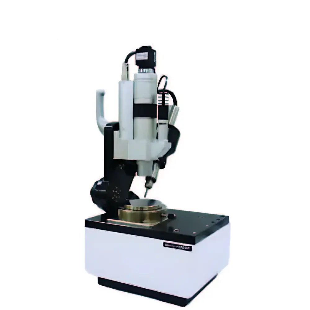
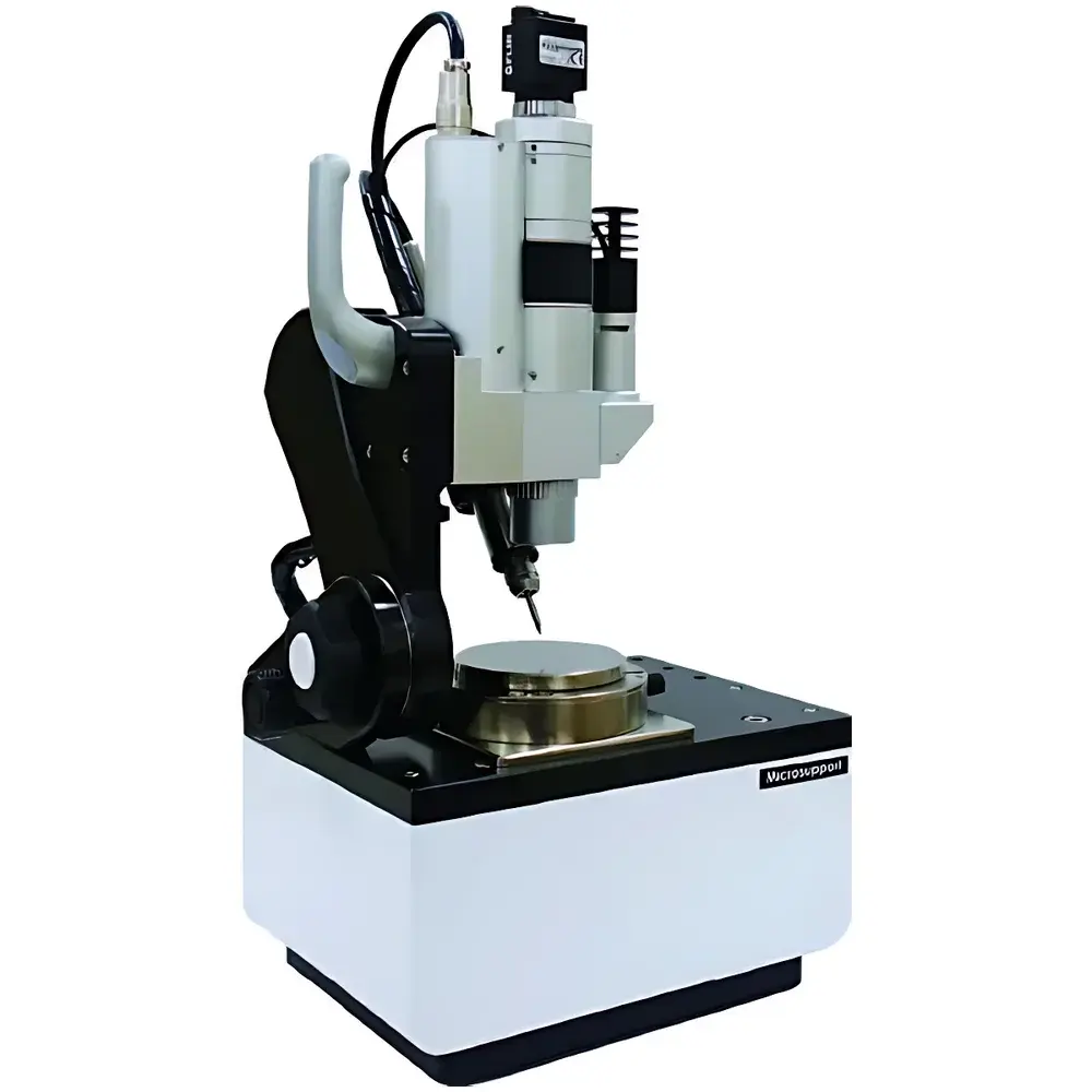
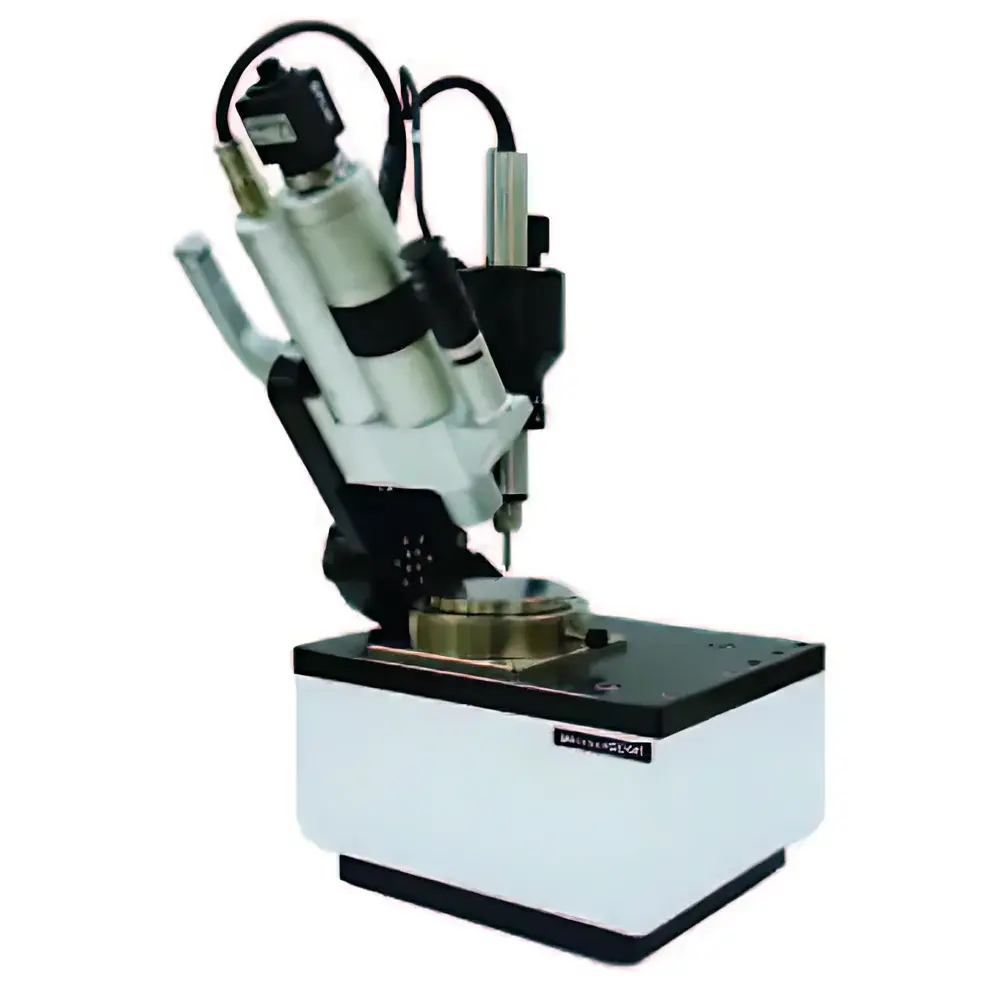
Micro Support Milling Scope MS-1 Integrated Micro-Machining and Observation System
| Brand | Micro Support |
|---|---|
| Origin | Japan |
| Model | Milling Scope MS-1 |
| Type | Desktop Integrated Micro-Machining & Optical Observation System |
| Compliance | CE-marked, ISO 9001–certified manufacturing process |
| Software Interface | Windows-based proprietary control suite with GLP-compliant audit trail (21 CFR Part 11 ready) |
| Footprint | ≤ 210 × 297 mm (A4 size) |
| Max. Sample Height | 50 mm |
| Z-axis Resolution | 0.1 µm (motorized linear stage) |
| Optical Magnification Range | 3.5×–225× (motorized zoom objective with calibrated scale) |
| Mapping Capability | Automated tile-based image stitching (up to 1000×1000 µm field coverage) |
| Tool Positioning Accuracy | ±0.5 µm (closed-loop stepper + optical encoder feedback) |
Overview
The Micro Support Milling Scope MS-1 is an integrated desktop-scale micro-machining and high-resolution optical observation system engineered for precision material modification and real-time morphological assessment at the micrometer scale. Unlike conventional standalone microscopes or milling platforms, the MS-1 unifies coaxial optical imaging and CNC-controlled mechanical processing within a single compact architecture—enabling simultaneous visual feedback and physical intervention on the same focal plane. Its operational principle relies on coaxial illumination and telecentric optical path alignment, ensuring minimal parallax between viewing axis and tool axis. This design facilitates direct correlation between observed features and machined geometry—critical for applications requiring traceable, repeatable micro-feature fabrication under visual guidance. The system operates in ambient laboratory conditions without vacuum or inert gas requirements, making it suitable for rapid prototyping, failure analysis, and preparatory sample sectioning across materials science, biomedical engineering, and microelectronics R&D environments.
Key Features
- Coaxial optical-mechanical architecture: Motorized zoom microscope (3.5×–225×) aligned precisely with the Z-axis of the micro-milling spindle, eliminating registration drift during iterative observation–machining cycles.
- A4-footprint mechanical platform: Compact 210 × 297 mm base integrates XYZ motorized stages (0.1 µm Z-resolution), high-rigidity aluminum alloy frame, and vibration-damped optical table surface—designed for stable operation on standard lab benches.
- Automated mapping & mosaic imaging: Proprietary software controls sequential wide-field image acquisition across user-defined regions; algorithms perform sub-pixel alignment and photometric normalization to generate metrologically traceable panoramic maps (up to 1 mm² coverage).
- Pre-programmed machining workflows: Supports coordinate-based point registration (drill, cut, trench), depth-controlled milling, and multi-pass contouring—all executed with closed-loop positional feedback and real-time tool-tip visualization.
- Material-agnostic toolpath adaptability: Compatible with tungsten carbide, diamond-coated, and micro-endmill tooling (diameters from 10 µm to 500 µm); accommodates hardness ranges from polymers (Shore D 40) to sintered ceramics (HV 1800) via adjustable feed rate and spindle speed parameters.
Sample Compatibility & Compliance
The MS-1 accepts standard SEM stubs, glass slides, silicon wafers (up to 100 mm diameter), and irregularly shaped specimens up to 50 mm in height and 150 mm in lateral dimension. Clamping is achieved via vacuum chuck (optional magnetic or mechanical fixtures available). All optical components comply with JIS B 7151 (microscope calibration standards), while motion control firmware adheres to IEC 61800-5-2 for functional safety in industrial equipment. The system meets CE Directive 2014/30/EU (EMC) and 2014/35/EU (LVD); full technical documentation—including risk assessment reports and conformity declarations—is supplied with each unit. For regulated environments, audit trail logging, electronic signature support, and user-access-level configuration align with FDA 21 CFR Part 11 and EU Annex 11 requirements when operated with validated software configurations.
Software & Data Management
The MS-1 is controlled via Windows-based MicroSupport Control Suite v4.x, featuring dual-panel GUI: left-side for live video feed and measurement overlays (distance, area, angle, profile line), right-side for machining parameter input (spindle RPM, feed rate, depth per pass, dwell time). All imaging and machining events are timestamped and logged with operator ID, instrument state, and environmental metadata (ambient temperature, humidity). Raw image data is stored in TIFF format with embedded EXIF tags; machining logs export as CSV or XML for LIMS integration. Optional add-ons include DIC-based strain mapping plugin and third-party API (RESTful) for integration into automated lab workflows.
Applications
- Materials science: Site-specific cross-sectioning of metallographic samples, FIB-free TEM lamella preparation, grain boundary milling for EBSD analysis.
- Biomedical research: Controlled ablation of dental enamel or cortical bone for histomorphometric studies; micro-drilling of bioresorbable polymer scaffolds for porosity validation.
- Microelectronics: Via opening on PCB prototypes, trimming of thick-film resistors, localized delamination of multilayer packages for root-cause failure analysis.
- Geosciences: Precision extraction of mineral inclusions from rock thin sections; micro-trenching for SIMS target preparation.
- Quality assurance labs: Non-destructive verification of coating thickness uniformity prior to destructive testing; micro-feature replication for gauge calibration.
FAQ
What is the maximum working distance achievable with the standard objective lens?
The standard telecentric objective provides a working distance of 42 mm at 3.5× magnification, decreasing to 12 mm at 225×—optimized for tool clearance during active milling.
Can the system be integrated with external analytical instruments (e.g., Raman spectrometers)?
Yes—the optical port supports C-mount and SM1-thread adapters; spectral coupling is possible via fiber-optic interface or side-port beam splitting (custom optical path design required).
Is training provided for operators unfamiliar with micro-machining protocols?
Micro Support offers certified on-site installation and two-day application-specific training covering safe operation, workflow scripting, image calibration, and GLP-aligned documentation practices.
How is tool wear compensated during extended machining sequences?
The system supports manual tool offset registration before each run; automatic wear compensation is not implemented but can be enabled via optional laser triangulation sensor module (sold separately).
Does the MS-1 meet ISO/IEC 17025 requirements for accredited testing laboratories?
While the MS-1 itself is not a measuring instrument per ISO/IEC 17025 Clause 6.4, its documented calibration procedures, traceable stage encoders, and software audit capabilities enable laboratories to establish metrological validity for in-house method development and internal QA processes.