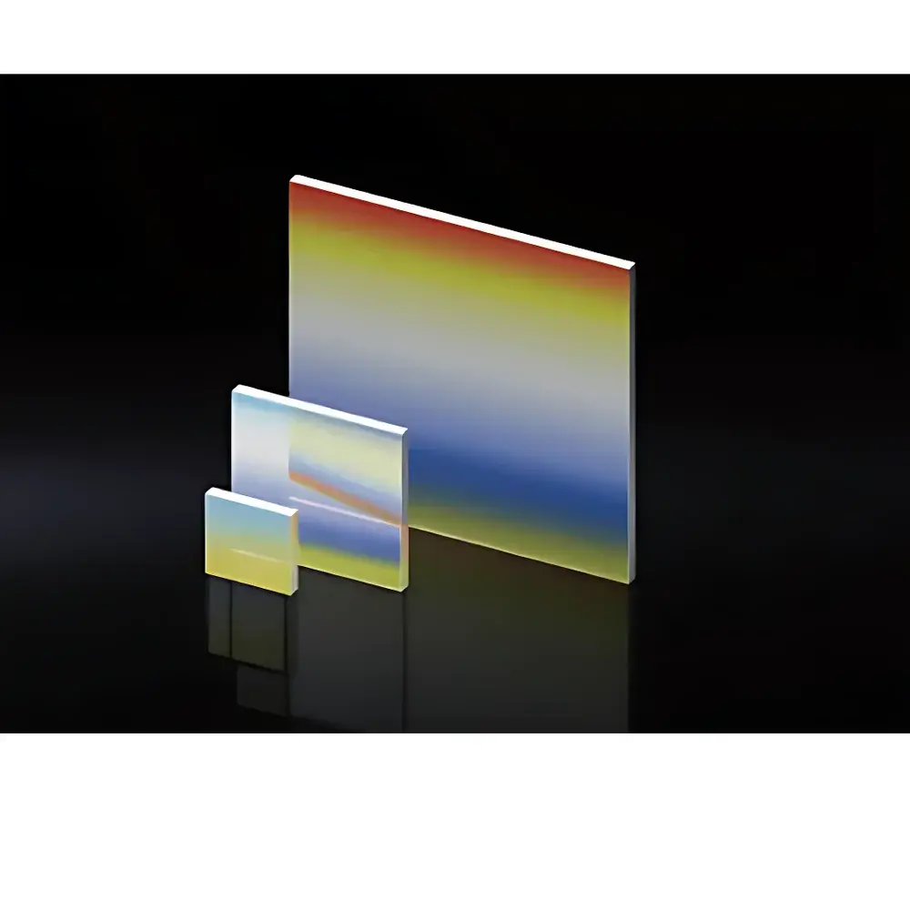
MiXran Meg1106 Transmission Grating Optical Component
| Brand | MiXran |
|---|---|
| Model | Meg1106 |
| Type | Transmission Diffraction Grating |
| Substrate Dimensions | 12.7 × 12.7 × 3 mm or 25 × 25 × 3 mm |
| Groove Density | 70–110 l/mm (configurable) |
| Design Wavelength | 632.8 nm (He–Ne) |
| Diffraction Orders | ±2, ±1, 0, +1, +2 |
| Typical Efficiency Distribution @632.8 nm | Specified per grating variant (e.g., GGR05-1313-7041, GGR05-2525-9245, etc.) |
| Material | Fused Silica (standard) |
| Coating | Uncoated or AR-coated (optional) |
| Compliance | ISO 10110-7 (surface quality), MIL-PRF-13830B (scratch-dig) |
Overview
The MiXran Meg1106 is a precision-engineered transmission diffraction grating designed for high-fidelity spectral dispersion in optical laboratory instrumentation. Based on the principle of constructive interference from periodic groove structures, it operates under the classical grating equation: nλ = d(sin θi + sin θn), where n is the diffraction order, λ the incident wavelength, d the groove period (inverse of groove density), θi the angle of incidence, and θn the angle of the nth-order diffracted beam. Unlike reflective gratings, the Meg1106 transmits incident light through its fused silica substrate—minimizing polarization-dependent loss and enabling compact, alignment-stable optical layouts in spectrometers, monochromators, wavelength calibration systems, and laser line separation modules. Its design prioritizes angular accuracy, wavefront fidelity, and long-term thermal-mechanical stability—critical for applications demanding repeatability across environmental fluctuations.
Key Features
- Precision ruled or holographically fabricated groove profiles with groove densities spanning 70 to 110 lines per millimeter—enabling tailored dispersion and resolution characteristics.
- Standard substrate options: 12.7 × 12.7 × 3 mm and 25 × 25 × 3 mm fused silica plates, polished to λ/10 surface flatness (per ISO 10110-3) and 20–10 scratch-dig specification (per MIL-PRF-13830B).
- Optimized efficiency distribution across ±2nd, ±1st, zeroth, and +1st orders at 632.8 nm—validated via calibrated CCD-based diffraction efficiency mapping under collimated He–Ne illumination.
- Low wavefront distortion (<0.125 wave PV @ 633 nm) ensures minimal aberration propagation in interferometric or imaging spectroscopy configurations.
- Optional broadband anti-reflection coating (R < 0.5% per surface, 400–1000 nm) available to suppress Fresnel reflections and enhance throughput in multi-grating or folded-path systems.
- Traceable metrology documentation provided: groove density uniformity ±0.05%, groove orientation tolerance ±2 arcmin, and centering error < ±0.1 mm relative to mechanical edges.
Sample Compatibility & Compliance
The Meg1106 is compatible with standard optomechanical mounting solutions—including kinematic lens tubes, SM1-threaded grating holders, and custom CNC-machined adapter plates. It supports collimated input beams with diameters up to 10 mm (12.7 mm variant) or 22 mm (25 mm variant) while maintaining specified diffraction efficiency and angular accuracy. All units are manufactured and tested in accordance with ISO 9001-certified processes. Surface quality, coating performance, and dimensional tolerances conform to ISO 10110-7 (optical component marking and testing), ISO 14997 (laser damage threshold testing), and RoHS Directive 2011/65/EU. For regulated environments (e.g., ISO/IEC 17025-accredited labs), full traceability to NIST-traceable interferometric and spectrophotometric standards is available upon request.
Software & Data Management
While the Meg1106 is a passive optical component, its integration into automated systems benefits from standardized optical design interoperability. Grating parameters—including groove density, blaze angle (where applicable), substrate refractive index (n = 1.458 @ 632.8 nm), and measured efficiency curves—are supplied in machine-readable CSV and Zemax-compatible .DAT formats. These files support direct import into optical simulation platforms (Zemax OpticStudio, CODE V, FRED) for system-level diffraction modeling and stray-light analysis. For laboratories operating under GLP or GMP frameworks, MiXran provides configurable calibration certificates with uncertainty budgets compliant with ISO/IEC 17025 Annex A.5, including measurement repeatability data and environmental sensitivity coefficients (e.g., Δd/d vs. temperature).
Applications
- Wavelength calibration references in UV-Vis-NIR spectrophotometers and portable Raman analyzers.
- Order-sorting elements in echelle spectrographs and compact Czerny–Turner monochromators.
- Laser line selection and harmonic separation in DPSS and Ti:sapphire laser systems.
- Teaching and research-grade optics kits for undergraduate and graduate photonics laboratories.
- Beam combining/splitting in heterodyne interferometry and optical coherence tomography (OCT) reference arms.
- Integration into OEM optical engines for environmental monitoring sensors (e.g., DOAS, cavity-enhanced absorption spectrometers).
FAQ
What is the maximum recommended input power density for continuous-wave lasers?
For uncoated fused silica substrates at 632.8 nm, the damage threshold exceeds 500 MW/cm² (10 ns pulse, 10 Hz); for CW operation, thermal lensing becomes limiting above 10 W/cm²—mounting on copper or aluminum heat-sink carriers is advised for >5 W average power.
Can the Meg1106 be used in vacuum or UHV environments?
Yes—fused silica substrates and optional ion-beam-sputtered AR coatings are outgassing-compliant per ASTM E595; bake-out stable to 150°C for 24 hours.
Is groove density uniformity verified across the entire aperture?
Yes—each unit undergoes full-aperture interferometric groove pitch mapping using a phase-shifting Twyman–Green interferometer; non-uniformity is reported in the certificate of conformance.
Do you offer custom groove profiles (e.g., blazed, sinusoidal, or binary)?
Custom holographic or ion-etched profiles—including blazed transmission gratings optimized for Littrow configuration at specific wavelengths—are available under NDA with lead times of 8–12 weeks.
How is angular alignment tolerance defined for optimal efficiency?
Incident beam alignment must be maintained within ±0.5° of nominal Littrow or normal incidence (as specified per part number); misalignment beyond ±1.0° induces measurable efficiency roll-off (>10%) and order asymmetry.