Olympus Dual-Arm Ultrasonic Through-Transmission Inspection System
| Brand | Olympus |
|---|---|
| Origin | Shanghai, China |
| Manufacturer Type | Authorized Distributor |
| Product Origin | Domestic (China) |
| Model | Custom-Configured Dual-Arm UT System |
| Pricing | Upon Request |
| Application Domain | Composite Structural Integrity Assessment |
Overview
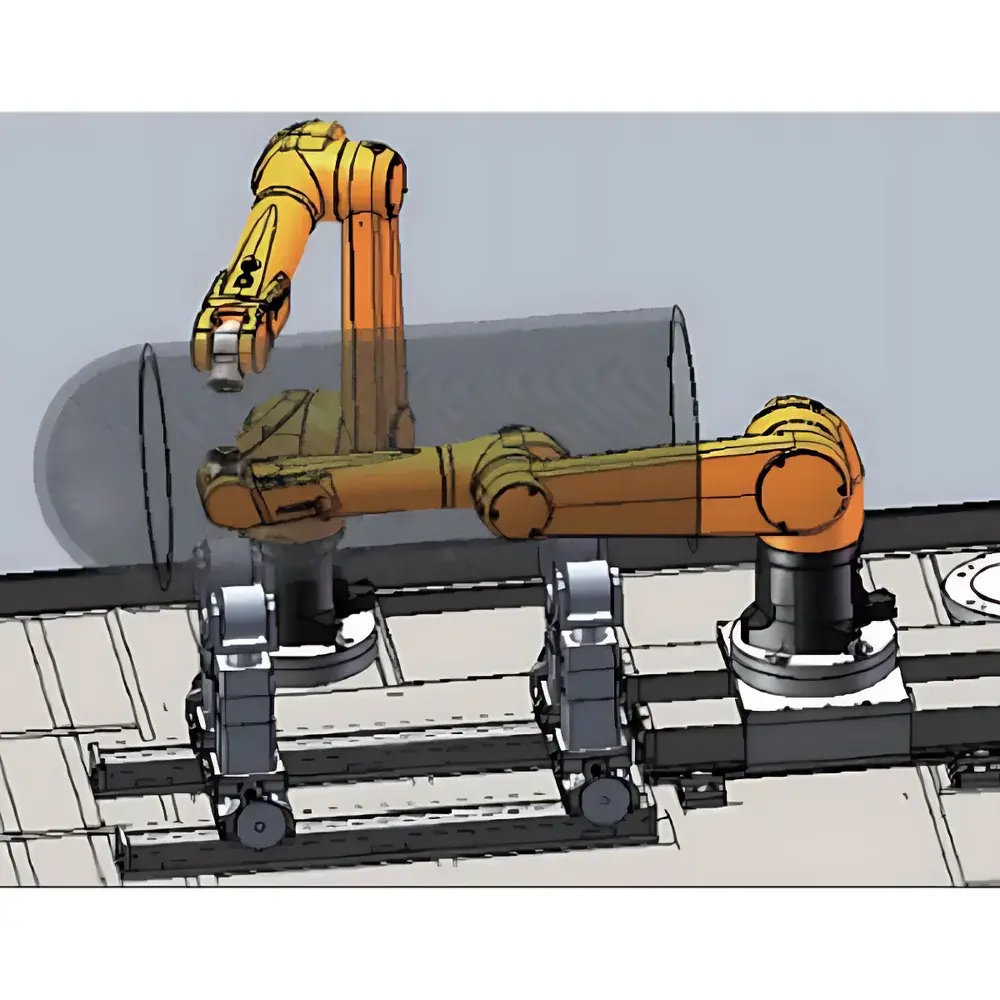
The Olympus Dual-Arm Ultrasonic Through-Transmission Inspection System is an engineered solution for high-fidelity non-destructive evaluation (NDE) of complex-curved composite components—particularly carbon fiber reinforced polymer (CFRP) structures used in aerospace, wind energy, and advanced transportation sectors. Unlike conventional single-probe ultrasonic systems constrained by fixed geometry or manual alignment, this system implements synchronized dual robotic arms to maintain orthogonal incidence of both transmitting and receiving ultrasonic beams relative to the local surface normal across continuously varying curvatures. The core measurement principle relies on through-transmission ultrasonics (TTU), where attenuation, time-of-flight (TOF), and signal amplitude ratios between transducer pairs are quantitatively correlated with volumetric discontinuities—including porosity, delamination, resin-rich zones, and fiber misalignment. By ensuring consistent acoustic coupling geometry independent of surface topology, the system delivers superior repeatability and spatial resolution compared to manual or gantry-based alternatives.
Key Features
- Dual 6-axis industrial robotic arms with real-time coordinated motion control, enabling dynamic maintenance of perpendicular beam incidence on freeform curved surfaces up to ±15° local curvature gradient.
- Modular transducer interface supporting both air-coupled ultrasonic probes (250 kHz–1 MHz) and water-jet coupled immersion-style probes (1–10 MHz), with automatic switching and calibration traceability.
- Integrated structured-light 3D scanner delivering sub-millimeter point cloud resolution (≤0.1 mm lateral, ≤0.05 mm depth) over scanning volumes up to 1,200 × 800 × 600 mm.
- Offline programming environment with native 16-axis kinematic solver for collision-free trajectory generation, motion simulation, and digital twin synchronization with CAD models (STEP, IGES, STL).
- Ruggedized industrial enclosure rated IP54, compliant with ISO 13849-1 for functional safety and EN 61000-6-2/6-4 for electromagnetic compatibility.
Sample Compatibility & Compliance
The system accommodates CFRP laminates ranging from 1 mm to 50 mm thickness, including sandwich structures with honeycomb or foam cores. It supports inspection of molded parts with radii as low as 30 mm and compound curvatures typical of wing skins, fuselage panels, and turbine blade roots. All hardware and software modules conform to ASTM E2737-21 (Standard Practice for Ultrasonic Testing Using Through-Transmission Technique), ISO 17847:2017 (Ultrasonic testing — Characterization of ultrasonic examination systems), and support GLP/GMP-aligned documentation workflows. Audit trails, user access levels, and electronic signatures are configurable to meet FDA 21 CFR Part 11 requirements when deployed in regulated manufacturing environments.
Software & Data Management
The proprietary inspection software suite includes three tightly integrated modules: (1) Surface Reconstruction Engine, which processes raw point cloud data into NURBS-based surface models and exports curvature maps for probe path optimization; (2) TTU Acquisition Module, featuring real-time A-scan/B-scan/C-scan synthesis, gated amplitude analysis, and differential attenuation mapping; and (3) Reporting & Archiving Framework, generating PDF/HTML reports with embedded C-scan images, positional metadata, and calibration certificates. Data export complies with ASME BPVC Section V, Article 4 formats and supports direct integration with enterprise quality management systems (QMS) via OPC UA or RESTful API interfaces.
Applications
This system is routinely deployed for production-level screening of CFRP aircraft fairings and empennage components, post-cure verification of thermoplastic composites in automotive battery enclosures, and R&D validation of additive-manufactured hybrid metal-composite joints. It enables quantitative defect sizing per ASTM E2375-22, supports statistical process control (SPC) charting of ultrasonic transmission coefficients across batch runs, and facilitates correlation studies between ultrasonic attenuation and mechanical properties derived from destructive coupon testing (e.g., ILSS per ASTM D2344).
FAQ
What types of couplant media are supported?
Air-coupled transducers (no couplant required) and water-jet coupling (using deionized water at 0.2–0.5 MPa pressure) are both natively supported.
Can the system inspect painted or coated CFRP surfaces?
Yes—structured-light scanning operates independently of surface finish, and air-coupled UT is unaffected by thin paint layers (<100 µm); water-jet coupling requires localized coating removal only where beam entry/exit occurs.
Is offline programming compatible with third-party CAD platforms?
Yes—native import of STEP AP242, IGES, and Parasolid XT files; neutral mesh formats (STL, PLY) are accepted for surface reconstruction.
Does the system provide traceable calibration documentation?
Each installation includes NIST-traceable transducer sensitivity reports, robot positional accuracy certification (per ISO 9283), and annual recalibration protocols aligned with ISO/IEC 17025.
What is the maximum scan area per setup without repositioning?
With standard arm configuration and optional linear rails, the effective unattended inspection envelope is 1,500 × 1,000 × 400 mm; larger parts require multi-station registration using fiducial markers.


