Olympus Wind Turbine Roller Ultrasonic Testing System
| Brand | Olympus |
|---|---|
| Origin | Shanghai, China |
| Manufacturer Type | Authorized Distributor |
| Product Origin | Domestic (China) |
| Detection Method | Pulse-Echo Ultrasonic Testing with Equivalent Flat-Bottom Hole (FBH) Calibration |
| Sensitivity | 0.5 mm × 0.5 mm FBH |
| Channel Capacity | Up to 4 Independent UT Channels |
| Automation Interface | Compatible with Robotic Arms & Overhead Cranes Integrated with Machine Vision |
| Software | Proprietary Real-Time UT Analysis Platform with Offline CAD-Based Path Planning, Zonal Defect Classification (Functional vs. Non-Functional Areas), Auto-Report Generation, Remote Supervisory Control, and MES/ERP Integration Capability |
| Compliance Framework | Designed to Support ISO 10893-3, ASTM E273, EN 13660, and GLP/GMP-aligned audit trails |
Overview
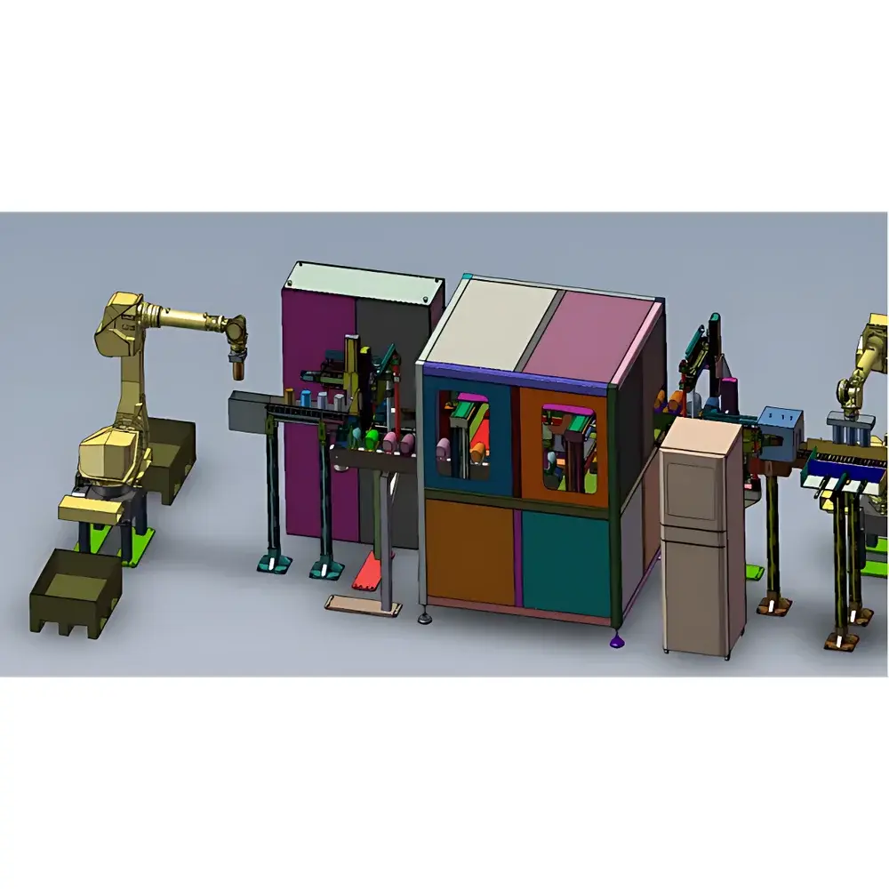
The Olympus Wind Turbine Roller Ultrasonic Testing System is a purpose-built, high-reliability non-destructive testing (NDT) platform engineered for the automated volumetric inspection of large-diameter cylindrical roller components used in wind turbine main shaft and pitch/yaw bearing assemblies. It employs pulse-echo ultrasonic technology calibrated against flat-bottom hole (FBH) reference standards—specifically optimized for detection of sub-surface discontinuities—including micro-cracks, inclusions, and forging laps—in high-alloy bearing steels (e.g., AISI 52100, 100Cr6, and equivalent grades). Unlike generic UT systems, this configuration integrates hardware synchronization, multi-channel signal acquisition, and physics-based flaw sizing algorithms tailored to the geometric and metallurgical constraints of forged and ground rollers operating under extreme cyclic loading conditions. The system is deployed in high-throughput manufacturing and in-service maintenance environments where traceability, repeatability, and compliance with international NDT certification requirements (e.g., ISO 9712 Level II/III operator workflows) are mandatory.
Key Features
- Four-channel synchronized ultrasonic acquisition architecture enabling concurrent A-scan data capture from multiple transducer orientations—critical for full circumferential coverage without mechanical repositioning delays.
- Integrated robotic interface supporting programmable motion control via industrial robot controllers (e.g., KUKA, ABB, FANUC) and overhead crane positioning systems, coupled with vision-guided part centering and orientation verification prior to scanning.
- Proprietary UT software platform featuring real-time echo analysis, dynamic gain compensation, and time-of-flight diffraction (TOFD)-enhanced sizing for planar defects—fully compliant with ISO 10893-3 Annex B guidelines for roller inspection.
- Automated functional zone mapping: software allows user-defined geometry-based segmentation (e.g., raceway contact bands, fillet transitions, shoulder zones) and applies distinct acceptance criteria per region per ASTM E273 Table 2 severity thresholds.
- Offline CAD-based path planning engine that imports STEP or IGES models to simulate probe travel paths, calculate beam incidence angles, and pre-validate coverage before physical setup—reducing commissioning time by up to 60%.
- Secure remote access architecture supporting encrypted VNC-based supervision, real-time dashboard telemetry (scan progress, channel health, signal-to-noise ratio trends), and over-the-air firmware updates with version-controlled rollback capability.
Sample Compatibility & Compliance
The system accommodates rollers with diameters ranging from 120 mm to 1,200 mm and lengths up to 2,500 mm, including tapered, cylindrical, and spherical roller geometries. Material compatibility extends across through-hardened and case-carburized bearing steels, as well as austenitic stainless variants used in offshore applications. All measurement protocols align with ISO 10893-3 (non-magnetic steel components), EN 13660 (rolling element bearing parts), and ASTM E273 (longitudinal beam ultrasonic examination of seamless pipe and tubing). Audit trail functionality meets FDA 21 CFR Part 11 requirements for electronic records and signatures when configured with role-based user authentication and immutable log archiving.
Software & Data Management
The embedded software suite operates on a Windows 10 IoT Enterprise platform and provides native support for OPC UA and MQTT protocols to enable bi-directional data exchange with MES (e.g., Siemens Opcenter, Rockwell FactoryTalk), QMS (e.g., ETQ Reliance), and CMMS platforms. Each inspection record includes raw RF waveform data, processed C-scan/B-scan images, defect coordinates (X/Y/Z in millimeters relative to part datum), and classification metadata (e.g., “functional-zone crack – length 1.2 mm, depth 0.4 mm, orientation 78°”). Reports are exportable in PDF/A-2b, XML (ASTM E1318-20), and CSV formats—with configurable templates adhering to customer-specific quality documentation standards.
Applications
- Pre-shipment inspection of new wind turbine main shaft rollers supplied to OEMs such as Vestas, GE Renewable Energy, and Goldwind.
- In-service condition monitoring of field-returned rollers undergoing remanufacturing or life-extension assessment.
- Process validation during heat treatment and grinding operations to detect quench cracks or grinding burns not visible via surface methods.
- Support for ISO 55001 asset management programs by linking UT-derived defect metrics to remaining useful life (RUL) modeling frameworks.
FAQ
Does the system support phased array ultrasonic testing (PAUT) in addition to conventional UT?
Yes—hardware architecture supports both single-element and matrix-array probes; PAUT modules can be enabled via optional firmware license and calibrated using ASME Section V Article 4 procedures.
Can inspection parameters be locked to prevent unauthorized modification during production runs?
Yes—role-based access control (RBAC) enforces parameter lockout at operator, supervisor, and administrator levels, with change logs recorded in tamper-evident audit files.
Is third-party calibration certificate traceable to NIST or PTB standards available?
Calibration reports issued by Olympus-certified service centers include traceability to national metrology institutes and comply with ISO/IEC 17025 requirements.
What is the typical lead time for site-specific integration with existing robotic cells?
Standard integration cycle is 8–12 weeks from mechanical interface definition to FAT, assuming availability of robot kinematic models and safety interlock schematics.


