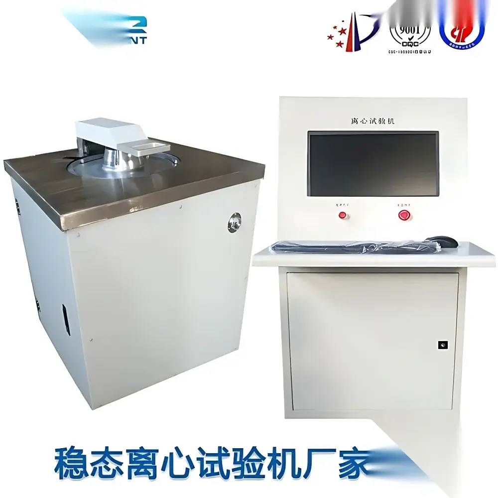
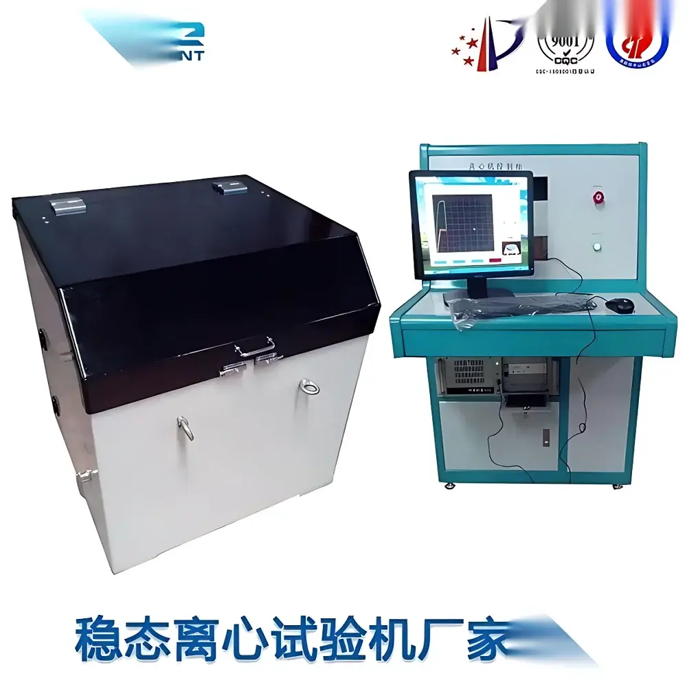
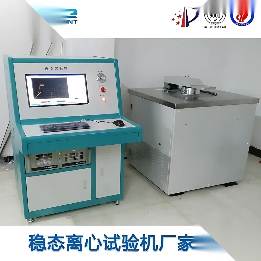
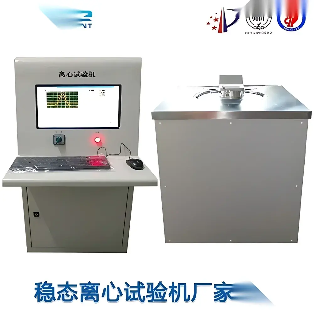
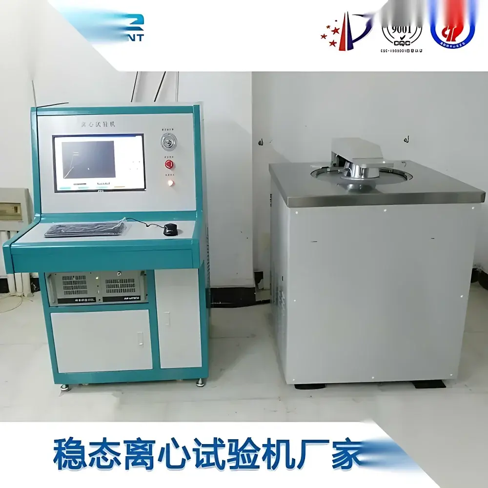
Stable Acceleration Centrifugal Test System
| Brand | Custom OEM |
|---|---|
| Origin | Imported |
| Manufacturer Type | Authorized Distributor |
| Price | USD 28,000 (FOB) |
Overview
The Stable Acceleration Centrifugal Test System is a precision-engineered dynamic overloading test platform designed to subject electronic components, microelectromechanical systems (MEMS), printed circuit board assemblies (PCBAs), and small-scale electro-mechanical devices to controlled, sustained centrifugal acceleration fields. Unlike transient shock or vibration testing, this system generates stable, steady-state inertial loading—simulating high-g-force environments such as launch dynamics, aircraft maneuvering, missile guidance system operation, or high-speed rotating machinery exposure. The core principle relies on rotational kinematics: acceleration (a) is calculated as a = ω²r, where angular velocity (ω) and radial distance (r) are precisely regulated via servo-controlled motor drive and real-time feedback from high-resolution encoders and load-cell–integrated mounting fixtures. Acceleration is expressed in SI units (m/s²), with traceable calibration against NIST-traceable reference accelerometers per ISO/IEC 17025 requirements.
Key Features
- Real-time industrial PC-based control architecture with deterministic loop timing (<5 ms update interval) for closed-loop acceleration regulation
- Multi-stage acceleration profile programming: up to 8 discrete acceleration levels per test sequence, each with independently set ramp rate (m/s²/s), dwell time (0.1–600 s), and tolerance band (±0.5% of setpoint)
- Dual-mode operation: fully automated test execution with preloaded MIL-STD-810F-compliant profiles, or manual jog mode with incremental acceleration stepping (0.1 g increments)
- Integrated safety interlock system: hardware-enforced over-acceleration cutoff (>105% setpoint), overspeed shutdown (via redundant tachometer monitoring), open-circuit detection on slip-ring channels, and emergency mechanical brake activation
- Modular slip-ring assembly: configurable 15-channel rotary electrical interface rated at 500 V AC / 5 A per channel, supporting signal integrity for analog sensor feeds (e.g., strain gauges, thermocouples) and digital I/O during rotation
- Structural mounting flexibility: adjustable radius arms (200–1000 mm center-to-center) enabling precise g-level tuning without mechanical reconfiguration
Sample Compatibility & Compliance
The system accommodates specimens up to 200 mm in height and supports triaxial testing—X, Y, and Z axes relative to the specimen’s functional orientation—by rotating the test fixture between runs using calibrated indexing plates. Mounting plates feature M4–M6 threaded arrays conforming to IPC-9701A mechanical interface standards. All configurations comply with military and international environmental test standards including: MIL-STD-810F Method 513.6 (Acceleration), MIL-STD-202G Method 213 (Centrifugal Force), MIL-STD-883K Method 2001 (Mechanical Shock and Acceleration), GJB 150.15A–2012, GJB 360B–2009, GB/T 2423.15–2008, and IEC 60068-2-27. Calibration certificates include uncertainty budgets compliant with ISO/IEC 17025:2017 and are issued by an ILAC-MRA accredited laboratory.
Software & Data Management
Control and analysis software runs on a Windows 10 IoT Enterprise OS platform with deterministic real-time extensions. It provides synchronized acquisition of acceleration, temperature, and auxiliary sensor data at ≥1 kHz sampling rate. All test sessions generate timestamped, digitally signed reports in PDF/A-1b format, including raw waveform exports (.CSV), pass/fail evaluation against user-defined tolerance envelopes, and automatic annotation of any deviation event. Audit trail functionality meets FDA 21 CFR Part 11 requirements, with role-based access control (admin/operator/viewer), electronic signatures, and immutable log retention for ≥15 years. Data export supports ASTM E1447-compliant metadata tagging for traceability in quality management systems (QMS) aligned with ISO 9001 and AS9100D.
Applications
- Qualification testing of avionics components under launch-phase g-loading (e.g., 100–50,000 m/s² range)
- Structural integrity validation of MEMS inertial sensors, RF switches, and piezoelectric actuators
- Reliability screening of solder joint fatigue resistance in high-density BGA packages
- Verification of adhesive bond strength in opto-electronic subassemblies subjected to sustained rotational stress
- Development testing of miniature UAV propulsion modules and gimbal stabilization mechanisms
- Failure mode analysis (FMA) of ceramic capacitors and thin-film resistors under constant acceleration-induced microstrain
FAQ
What acceleration ranges are supported across different models?
Standard configurations cover 30–2,000 m/s² (≈3–204 g), 50–1,000 m/s², and ultra-high-range variants up to 400,000 m/s² (≈40,800 g) — selected based on specimen mass, radius constraints, and required dwell stability.
Is third-party calibration included with delivery?
Yes — each system ships with a full factory calibration certificate (including linearity, hysteresis, and repeatability data) traceable to national metrology institutes. Optional annual recalibration services are available under ISO/IEC 17025 scope.
Can the system be integrated into an existing environmental test lab network?
Yes — Ethernet/IP and Modbus TCP interfaces enable seamless integration with LabVIEW, MATLAB, or enterprise MES/QMS platforms. SCADA-level alarm forwarding (SNMP v3) and OPC UA server support are standard.
Does the system meet GLP or GMP audit requirements?
Fully compliant: software includes 21 CFR Part 11–qualified electronic records, ALCOA+ data integrity principles, and configurable audit trail depth — validated per GAMP 5 guidelines for regulated laboratories.


