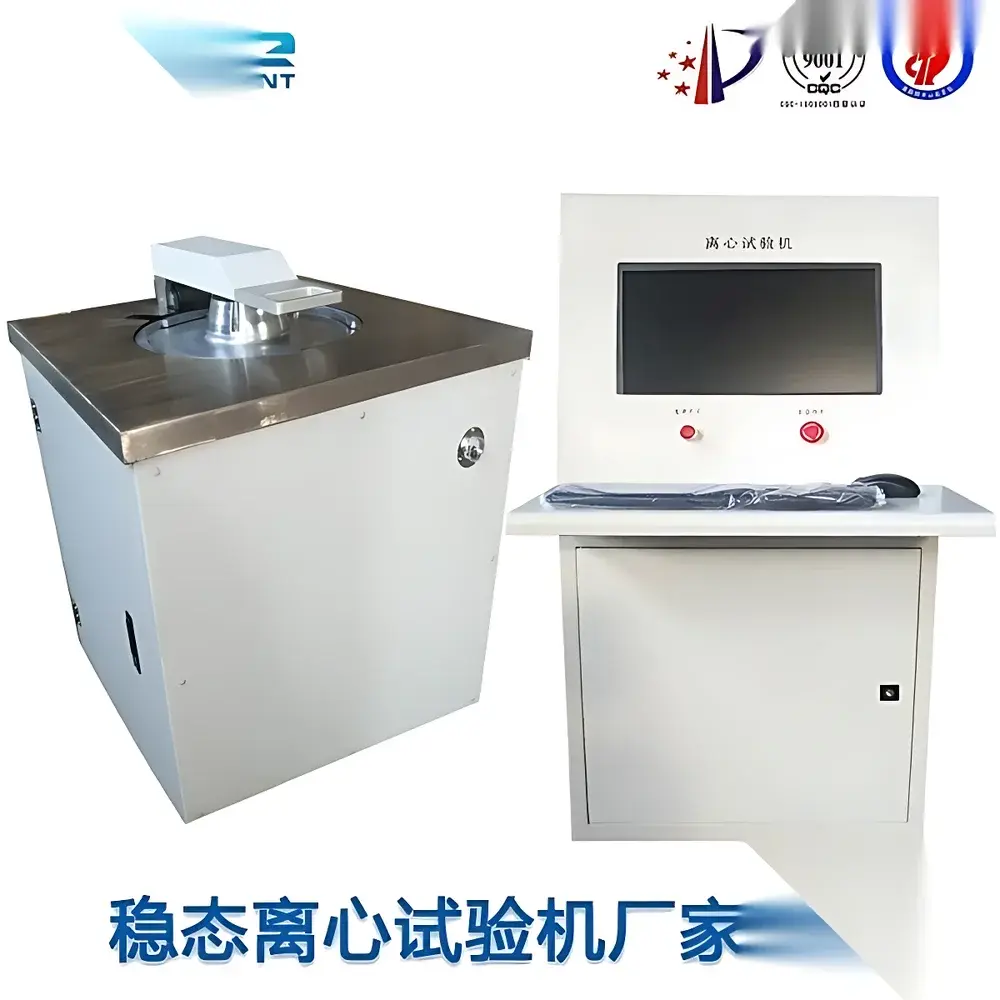
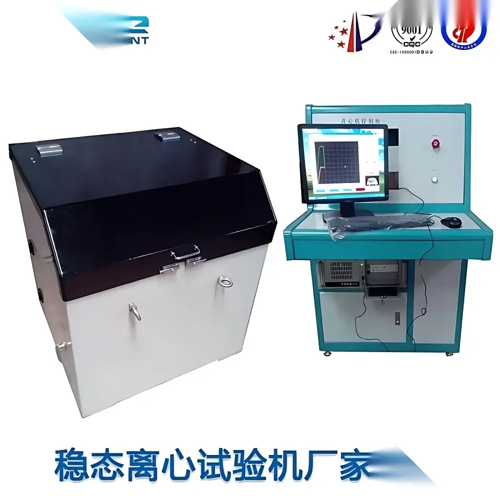
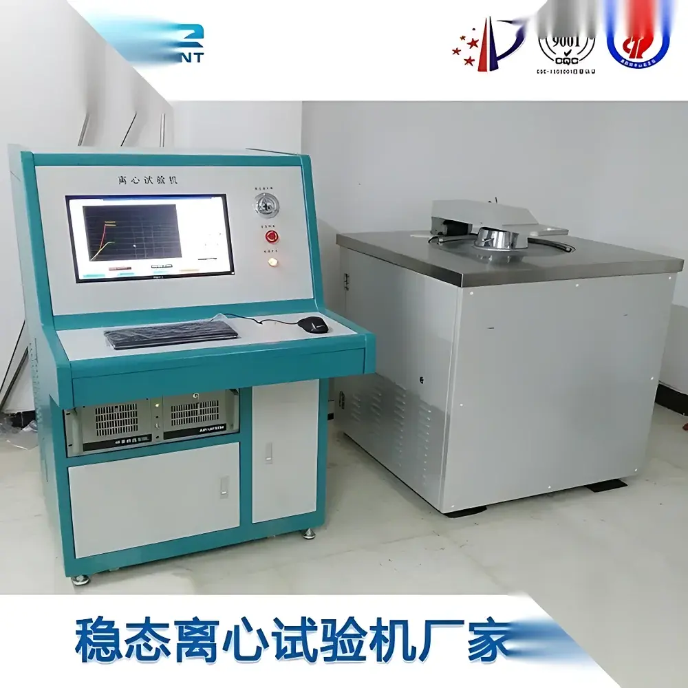
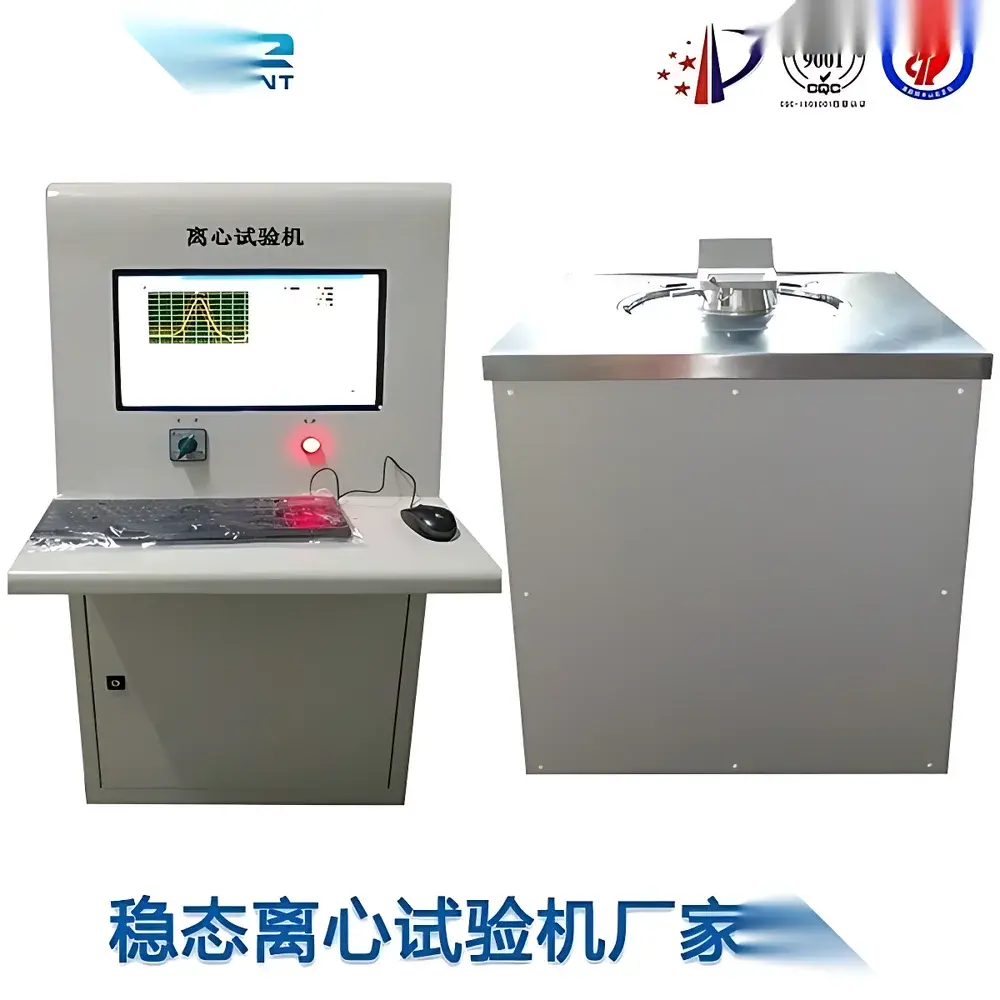
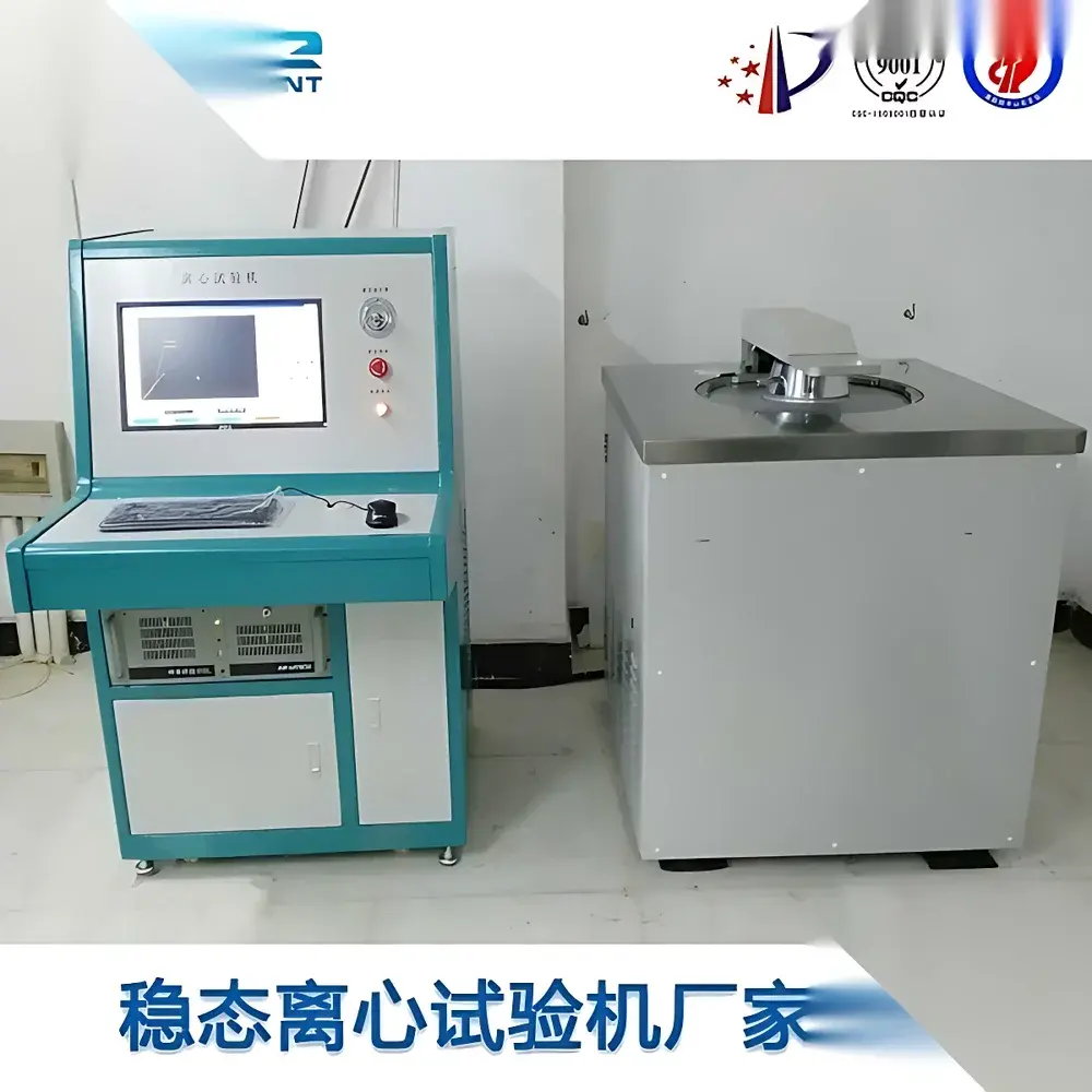
Steady-State Acceleration Centrifuge Test Chamber
| Brand | Other Brands |
|---|---|
| Origin | Imported |
| Manufacturer Type | General Distributor |
| Price | USD 28,000 (approx.) |
Overview
The Steady-State Acceleration Centrifuge Test Chamber is a precision-engineered mechanical stress testing system designed to subject electronic components, microelectromechanical systems (MEMS), avionics modules, and small-scale electro-mechanical devices to controlled, sustained radial acceleration fields. Unlike transient shock or vibration testing, this chamber generates stable, time-invariant centripetal acceleration via high-speed rotation—effectively simulating extreme gravitational loading environments (g-loads) ranging from 30 g to over 400,000 g, depending on configuration. The fundamental principle relies on Newtonian mechanics: centrifugal acceleration a = ω²r, where angular velocity (ω) and specimen radius (r) are precisely regulated to achieve target g-levels with high reproducibility. This enables structural integrity evaluation, solder joint fatigue assessment, bond wire reliability screening, and verification of mechanical stability under static over-acceleration conditions—critical for aerospace, defense, and high-reliability industrial electronics qualification.
Key Features
- Real-time industrial PC-based control system with deterministic timing resolution and closed-loop rotational speed regulation
- Automated test sequencing supporting multi-step acceleration profiles—including ramp-hold-ramp, stepwise g-level transitions, and dwell periods at defined acceleration magnitudes
- Integrated safety architecture featuring hardware-enforced over-speed cutoff, current-limiting slip-ring protection, open-circuit detection, and thermal monitoring of motor windings and bearing assemblies
- Dual-mode operation: fully automated script-driven execution or manual jog/override control with tactile feedback and emergency stop interlock compliance
- Modular slip-ring assembly with configurable channel count (up to 15 circuits) and electrical rating (500 V / 5 A per channel), enabling real-time telemetry acquisition (e.g., voltage, temperature, resistance) during acceleration exposure
- Triaxial test capability: specimens can be mounted and tested sequentially along X, Y, and Z axes relative to the centrifugal vector, accommodating orthogonal load-path validation per MIL-STD-810F and GJB150 requirements
Sample Compatibility & Compliance
The chamber accommodates specimens up to 200 mm in height (standard configuration) and supports mounting radii from 200 mm to 1000 mm—enabling g-level tuning across orders of magnitude without mechanical reconfiguration. Fixture interfaces comply with ISO 2768-mK general tolerancing standards, and load plates feature M4–M6 tapped holes for universal sample retention. The system meets full regulatory alignment with military and international environmental test standards, including:
– MIL-STD-810F Method 513.6 (Acceleration)
– MIL-STD-202G Method 213 (Centrifugal Force)
– MIL-STD-883H Method 2001 (Steady-State Acceleration)
– GJB 150.15A–2012 (Chinese military standard for steady-state acceleration testing)
– GB/T 2423.15–2008 (Chinese national standard equivalent to IEC 60068-2-27)
Software & Data Management
Control and data acquisition are managed via a Windows-based deterministic runtime environment with deterministic scheduling, timestamped analog/digital I/O logging (≥1 kHz sampling), and synchronized curve plotting. All test parameters—including setpoint acceleration, actual RPM, elapsed time, tolerance band status, and fault event logs—are recorded in CSV and binary formats compliant with GLP/GMP audit trail requirements. Exported reports include metadata headers (operator ID, calibration date, chamber serial number), pass/fail annotations against user-defined acceptance thresholds, and digital signatures supporting FDA 21 CFR Part 11 readiness when deployed in regulated quality systems.
Applications
- Qualification testing of inertial sensors, accelerometers, and gyroscopes under sustained g-load conditions
- Structural validation of PCB assemblies, chip-scale packages, and embedded passive components prior to flight or mission-critical deployment
- Reliability screening of MEMS actuators, RF switches, and piezoelectric transducers exposed to launch-phase acceleration environments
- Failure mode analysis of adhesives, encapsulants, and underfill materials subjected to differential thermal expansion under high-g stress
- Verification of mechanical latch integrity, spring-loaded contacts, and micro-switch actuation thresholds in avionics enclosures
FAQ
What is the maximum sustainable acceleration achievable with the LXJ series?
Maximum steady-state acceleration depends on model variant and specimen radius; configurations support up to 400,000 g at 1000 mm radius (LXJ-5 model), verified via traceable laser tachometry and NIST-traceable accelerometer calibration.
Does the system support real-time sensor data acquisition during rotation?
Yes—integrated slip-ring interface provides isolated power and signal transmission for up to 15 analog/digital channels, compatible with industry-standard DAQ modules (e.g., NI PXI, Keysight U2300A).
Is the control software validated for use in ISO 9001-certified laboratories?
The software includes version-controlled release notes, change logs, and IQ/OQ documentation templates aligned with ISO/IEC 17025 requirements for test equipment validation.
Can the chamber perform tests in accordance with US DoD contract requirements?
Yes—fully compliant with applicable sections of MIL-STD-810F, MIL-STD-883H, and DOD-STD-3017, with test reports structured to satisfy DFARS clause 252.246-7001 documentation mandates.


