Stresstech G2 Portable X-ray Residual Stress Analyzer
| Brand | Stresstech Oy |
|---|---|
| Country of Origin | Finland |
| Model | G2 |
| Portability | Field-deployable, integrated water-cooled X-ray generator |
| Safety Compliance | EN 61000-6-4, EN 61000-6-2, IEC 61000-4-3, CE-marked for industrial use |
| Detector Type | High-resolution silicon strip detector (SSD) or CCD-based imaging detector (configurable) |
| X-ray Source | Microfocus tungsten anode tube, 30–50 kV adjustable, <100 µm focal spot |
| Measurement Method | Sin²ψ technique with automated ψ-tilt stage (±45° range) |
| Data Acquisition | Real-time diffraction pattern capture, peak fitting via pseudo-Voigt deconvolution |
| Software Platform | RoboScan™ v5.x with GLP-compliant audit trail and 21 CFR Part 11-ready user access control |
Overview
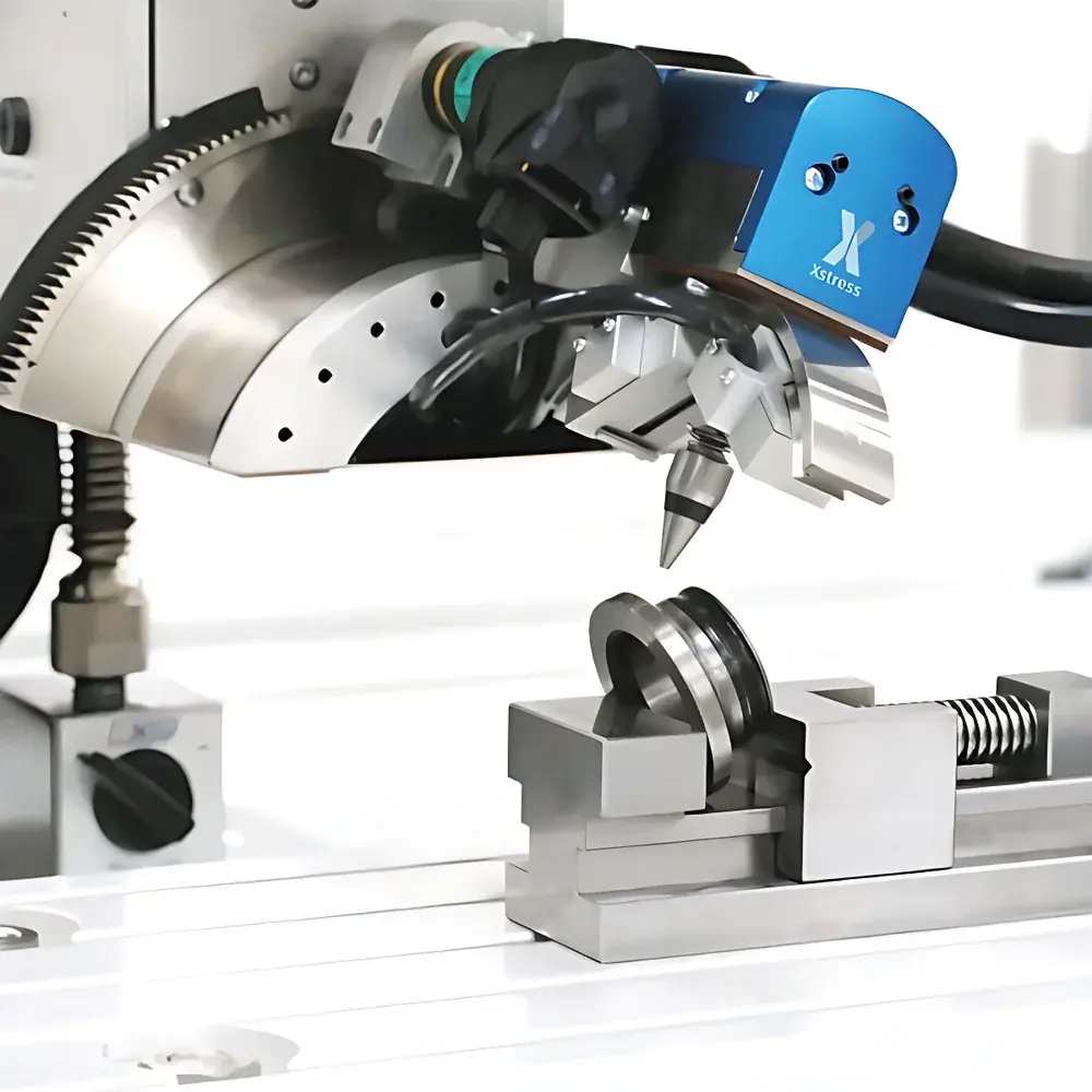
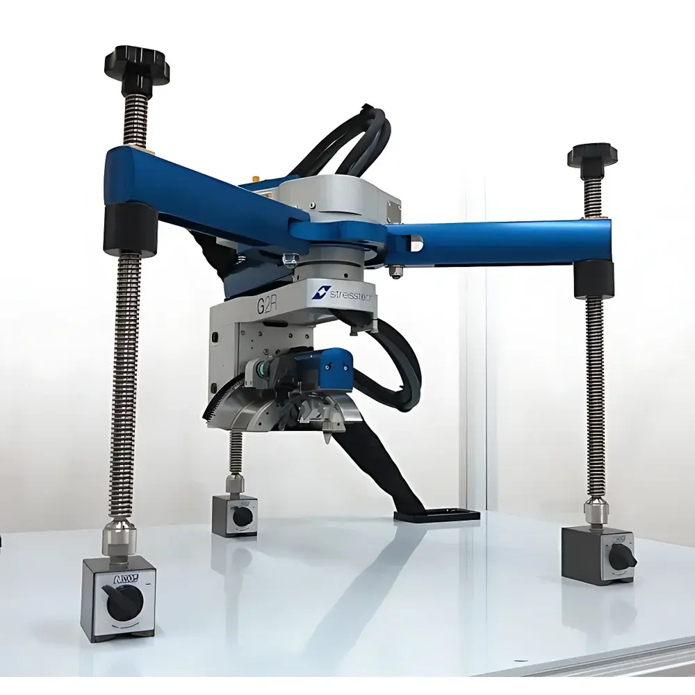
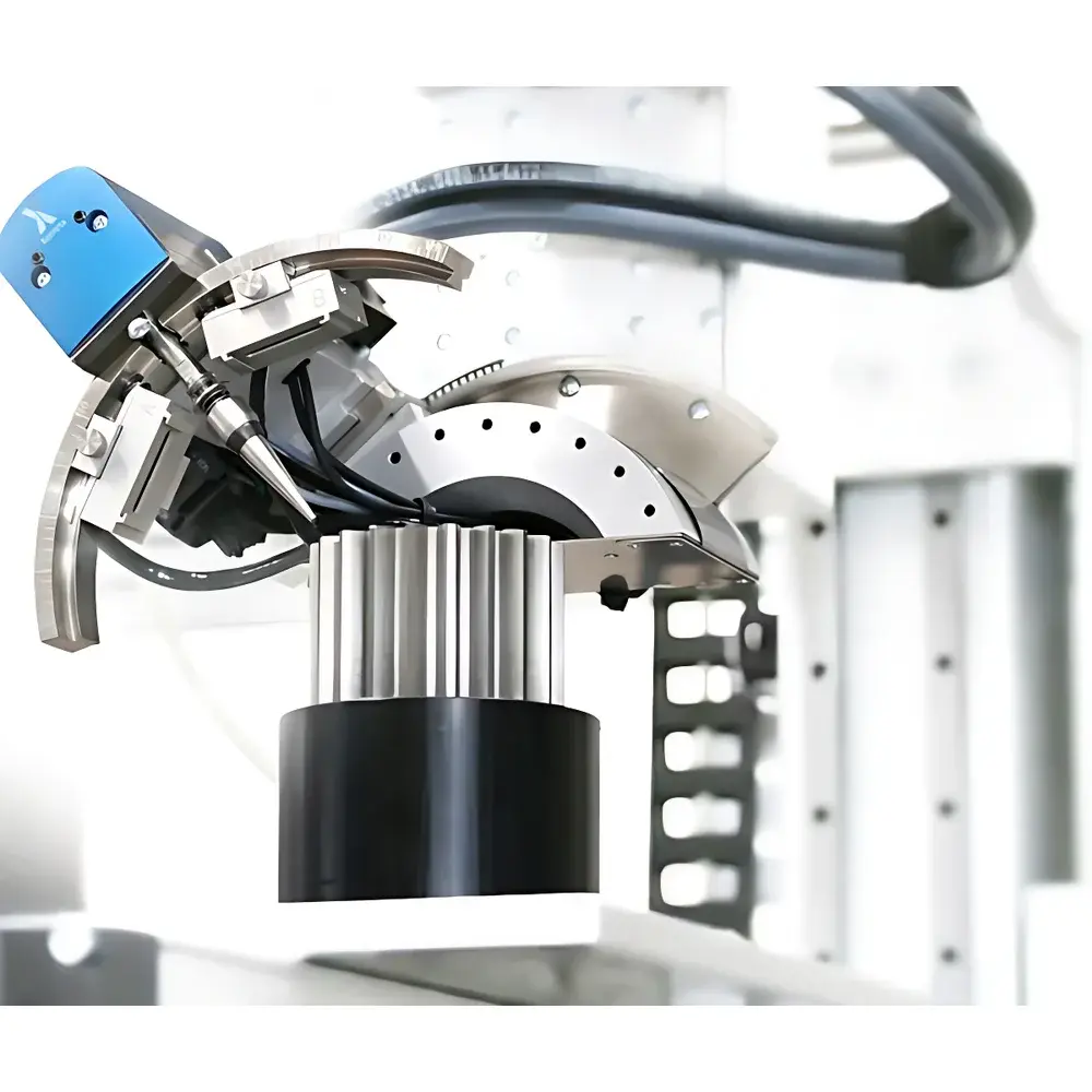
The Stresstech G2 Portable X-ray Residual Stress Analyzer is an engineered field-deployable instrument designed for quantitative measurement of near-surface residual stress in polycrystalline metallic components using the sin²ψ X-ray diffraction (XRD) method. Unlike laboratory-based benchtop diffractometers, the G2 integrates a microfocus X-ray tube, precision motorized ψ-tilt stage, high-sensitivity solid-state detector, and closed-loop self-circulating water cooling into a ruggedized, transportable enclosure—enabling in-situ stress evaluation directly on production floors, maintenance bays, or field sites without component removal. Its core principle relies on lattice strain determination via angular shift (Δ2θ) of crystalline diffraction peaks under systematically varied sample inclination angles (ψ), converted to stress values using elastic constants and the stress factor (E/(1+ν)). The system supports both uniaxial and biaxial stress states and delivers traceable results compliant with ASTM E915-22, ISO 21432:2020, and EN 15305:2021 standards.
Key Features
- Integrated water-cooled microfocus X-ray source (30–50 kV, tungsten target) ensuring stable intensity and minimal thermal drift during extended measurements
- Motorized, high-precision ψ-tilt stage with ±45° angular range and <0.02° repeatability for accurate sin²ψ data acquisition
- Configurable detection options: high-count-rate silicon strip detector (SSD) for rapid single-peak analysis or CCD-based area detector for full-pattern collection and phase identification
- Ruggedized aluminum chassis with IP54-rated enclosure, shock-mounted internal optics, and ergonomic carrying handles for industrial environments
- Dual safety architecture: hardware interlocks (door switches, beam shutter sensors) plus software-enforced exposure limits and real-time dose monitoring per IEC 61547-1
- Onboard calibration verification using certified reference samples (e.g., stressed Inconel 718 or Al 2024 standards)
Sample Compatibility & Compliance
The G2 accommodates flat, curved, or irregularly shaped metallic parts—including gears, bearing races, crankshafts, camshafts, turbine blades, weld joints, and pressure vessel nozzles—with surface roughness up to Ra 6.3 µm and minimum radius of curvature ≥25 mm. It supports ferrous alloys (steel, cast iron), non-ferrous metals (Al, Ti, Ni-based superalloys), and hard-coated substrates (e.g., CrN, WC-Co) when equipped with appropriate anode/filter combinations (e.g., Cr Kα for steel, Co Kα for nickel alloys). All measurement protocols adhere to ISO/IEC 17025:2017 requirements for testing laboratories, and raw diffraction data files are stored in vendor-neutral .xye or .raw formats compatible with third-party Rietveld refinement tools. Full documentation packages—including IQ/OQ/PQ protocols, uncertainty budgets per GUM (JCGM 100:2008), and traceable calibration certificates—are provided for regulated industries.
Software & Data Management
RoboScan™ v5.x serves as the unified control, acquisition, and analysis environment. It features automated peak search with adaptive background subtraction, iterative least-squares fitting using pseudo-Voigt line profiles, and built-in stress tensor calculation modules for both macro- and micro-stress evaluation. The software enforces role-based access control (RBAC), electronic signatures, and immutable audit trails meeting FDA 21 CFR Part 11 and EU Annex 11 requirements. Measurement reports include full metadata (instrument ID, operator, date/time, environmental conditions, collimator size, exposure time), uncertainty estimates per ISO/IEC 17025, and export options to PDF, Excel, or XML for integration into LIMS or MES platforms. Optional modules support automated reporting templates aligned with ASME BPVC Section V, API RP 579, or NADCAP AC7114.
Applications
- Verification of stress relief efficacy after welding, heat treatment, or shot peening in aerospace structural components
- In-process monitoring of grinding-induced tensile stresses in bearing races and cam lobes to prevent thermal damage
- Quantitative assessment of compressive residual stress depth profiles in gear teeth following roller burnishing
- Root cause analysis of premature fatigue failure in turbine disks and compressor blades
- Validation of surface integrity in additive-manufactured titanium parts prior to HIP and machining
- Residual stress mapping across weld seams in pipeline girth welds for integrity management programs
FAQ
What is the typical measurement depth range for the G2 system?
The penetration depth depends on material density and X-ray energy; for steel at 40 kV with Cr Kα radiation, the effective measurement depth is approximately 10–25 µm. Depth profiling is achievable via electrochemical layer removal or sequential etching under controlled conditions.
Can the G2 measure residual stress in coated components?
Yes—provided the coating thickness is ≤5 µm and the substrate exhibits sufficient diffraction intensity. Thin-film stress analysis requires optimized incidence angles and monochromatic filtering to isolate substrate peaks.
Is operator radiation safety training required?
Yes. While the G2 meets all regulatory dose-rate limits (<1 µSv/h at 5 cm), users must complete site-specific radiation safety training and wear personal dosimeters in accordance with national regulations (e.g., NRC 10 CFR 20, IRR2017).
How is measurement uncertainty quantified and reported?
Uncertainty is calculated per ISO/IEC 17025 Annex A using Type A (statistical repeatability) and Type B (calibration, alignment, peak fitting) components, with combined standard uncertainty typically ≤35 MPa for steel under optimal conditions.
Does the system support automated scanning over large areas?
Not natively—the G2 is optimized for discrete point measurements. For mapping, optional motorized XY stages (sold separately) integrate via RoboScan™’s external motion control API, enabling programmable grid-based acquisition with positional synchronization.
Related Products
")