
Stresstech Oy XStress Robotic Residual Stress Analysis System
| Brand | Stresstech Oy |
|---|---|
| Origin | Finland |
| Model | XStress |
| Type | Robotic X-ray Diffraction (XRD)-Based Residual Stress Analyzer |
| Detection Principle | Sin²ψ Method with Monochromatic Cu Kα or Cr Kα Radiation |
| Detector Technology | Solid-State Linear Pixel Array Detector |
| Safety Compliance | EN 61000-6-4, EN 61000-6-2, IEC 61508 SIL2 (Embedded Interlock Architecture) |
| Software Platform | XTronic v5.2 (FDA 21 CFR Part 11 Compliant Audit Trail, GLP/GMP-Ready Reporting) |
| Robotic Integration | 6-Axis Industrial Robot with Real-Time Path Compensation and Surface Normal Tracking |
Overview
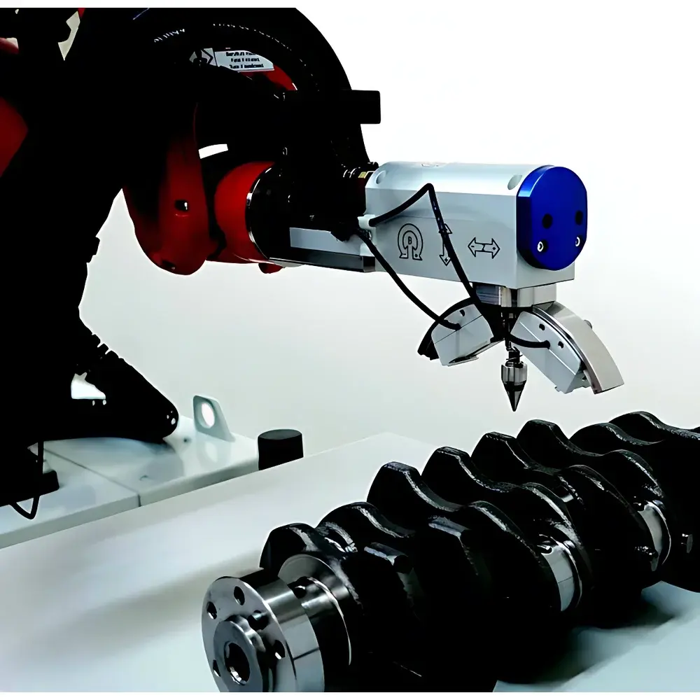
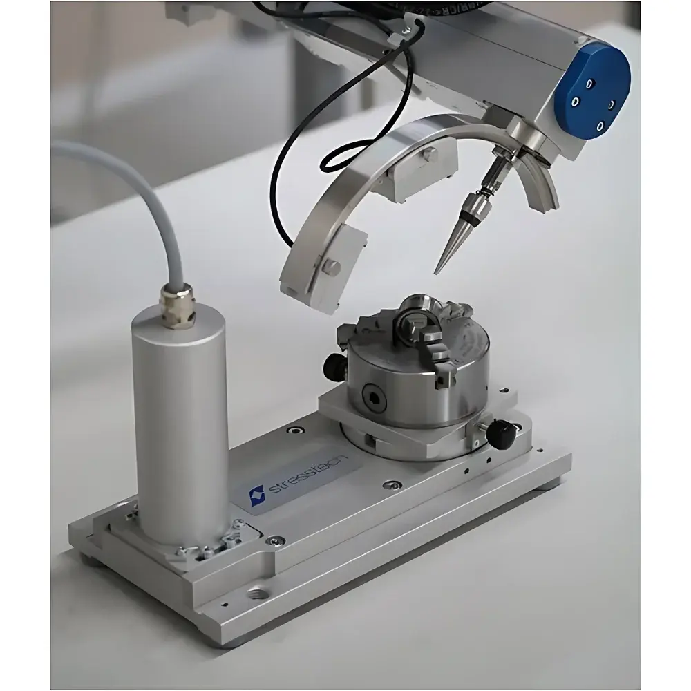
The Stresstech Oy XStress Robotic Residual Stress Analysis System is a fully integrated, automation-ready X-ray diffraction (XRD) platform engineered for high-precision, non-destructive residual stress mapping on complex industrial components. Unlike conventional benchtop X-ray stress analyzers, the XStress robotic system couples a motorized G3 goniometer—mounted directly onto a 6-axis industrial robot arm—with a solid-state linear pixel array detector and monochromatic X-ray source (Cu Kα or Cr Kα). This architecture implements the sin²ψ method in accordance with ASTM E915-22, ISO 21432:2020, and EN 15305:2021 standards, enabling quantitative determination of near-surface (typically 10–50 µm depth) lattice strain in crystalline metallic materials. The system’s core innovation lies in its real-time coordinate transformation engine: as the robot repositions the goniometer, the XTronic software dynamically recalculates incident angle, diffraction geometry, and surface normal orientation—eliminating manual sample repositioning and enabling true 3D contour-following measurements on turbine blades, weld joints, forged gears, and curved pressure vessel sections.
Key Features
- Robotic Goniometer Integration: G3 tube-handling unit rigidly mounted to a high-repeatability 6-axis industrial robot (±0.02 mm positional accuracy), enabling full 360° azimuthal rotation and ±90° tilt around the measurement point.
- Adaptive Surface Tracking: On-the-fly surface normal estimation via laser triangulation or CAD-based path planning; supports automated mapping of stress gradients across freeform geometries without manual intervention.
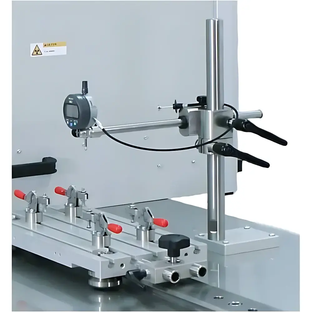
- Modular Collimation System: Interchangeable robotic collimators (1, 2, and 4 mm diameters) optimized for micro-area analysis on small features (e.g., gear teeth root radii) or large-area averaging on thick-walled structures.
- Embedded Safety Architecture: Dual-channel hardware interlocks compliant with IEC 61508 SIL2, including beam shutter control, emergency stop propagation, and zone monitoring—certified for integration into ISO 13849-1 Category 3 machinery safety circuits.
- Material-Aware Calibration: Pre-loaded crystallographic databases for Al, Ti, Ni, Fe, and Co-based alloys; automatic lattice parameter correction for textured materials (e.g., rolled aluminum, additively manufactured Ti-6Al-4V) using multi-peak fitting algorithms.
Sample Compatibility & Compliance
The XStress robotic system accommodates samples ranging from 2 m long shafts or segmented turbine casings, provided they fit within the robot’s working envelope (typically Ø 2.5 m × H 2.2 m). It is validated for use with polycrystalline metals exhibiting sufficient diffracting power (e.g., FCC, BCC, HCP lattices), including cast, wrought, welded, and additive-manufactured microstructures. All measurement protocols adhere to ASTM E915-22 (Standard Test Method for Verifying the Alignment of X-Ray Diffraction Instrumentation for Residual Stress Measurement) and ISO 21432:2020 (Non-destructive testing — Test method for residual stress analysis by X-ray diffraction). Full traceability is maintained per ISO/IEC 17025:2017 requirements, with instrument calibration certificates traceable to NIST SRM 660c (LaB₆) and PTB reference standards.
Software & Data Management
XTronic v5.2 serves as the unified control, acquisition, and reporting engine. Its modular architecture separates motion planning (robot trajectory generation), data acquisition (real-time peak centroiding, background subtraction, and FWHM calculation), and post-processing (stress tensor decomposition, contour interpolation, and statistical outlier filtering). All user actions—including parameter changes, measurement initiation, and report export—are logged in an immutable, time-stamped audit trail compliant with FDA 21 CFR Part 11. Reports export in PDF/A-1b format with embedded metadata (sample ID, operator, calibration date, uncertainty budget per ISO/IEC 17025 Annex A.3), supporting GLP and GMP-regulated environments. Optional API integration enables direct linkage to MES (e.g., Siemens Opcenter) and PLM systems (e.g., Teamcenter) for automated stress data ingestion into digital twin workflows.
Applications
- Aerospace: Mapping tensile/compressive stress gradients across nickel-based superalloy turbine blades post-machining and shot peening; validation of thermal barrier coating adhesion integrity.
- Power Generation: Residual stress profiling in welded SA-508 Class 3 reactor vessel nozzles and dissimilar metal welds (Inconel 600/SA-508) per ASME Section III NB-2300 requirements.
- Automotive: Quantifying grinding burn-induced tensile stresses in case-hardened transmission gears; correlation with rolling contact fatigue life prediction models.
- Energy Infrastructure: In-situ stress evaluation of circumferential girth welds in subsea pipelines (API RP 2X compliance) and boiler tube expansion joints under operational thermal cycling.
- R&D Laboratories: High-throughput comparative studies of surface mechanical attrition treatment (SMAT), laser shock peening (LSP), and low-plasticity burnishing (LPB) efficacy across Ti-6Al-4V, IN718, and 316L SS substrates.
FAQ
Does the XStress robotic system require a dedicated radiation-shielded room?
No. The system operates in standard industrial environments when equipped with optional lead-acrylic viewing panels and perimeter warning lights. Its dose rate at 30 cm is <1.5 µSv/h during operation—well below EU Directive 2013/59/Euratom occupational exposure limits.
Can the robot automatically recognize part geometry without CAD input?
Yes. Optional laser scanning mode generates a point cloud prior to measurement, enabling automatic feature extraction (edges, holes, curvature centers) and adaptive path generation without preloaded CAD models.
How is measurement uncertainty quantified and reported?
Uncertainty budgets follow ISO/IEC Guide 98-3 (GUM) and include contributions from goniometer angular repeatability (±0.005°), detector pixel resolution (±0.002° 2θ), lattice parameter drift (<0.001 Å), and peak fitting residuals. Total expanded uncertainty (k=2) is displayed per measurement point in all reports.
Is remote diagnostics and software update support available?
Yes. Secure TLS 1.3-enabled remote access allows Stresstech Field Application Engineers to perform real-time troubleshooting, firmware updates, and calibration verification—subject to customer-defined network security policies.
What training and documentation are provided with system delivery?
Comprehensive on-site commissioning includes 3-day operator certification, 2-day maintenance technician training, and full documentation package: IEC 62061-compliant safety manual, ASTM/ISO test procedure templates, and raw data format specification (HDF5-based binary schema with metadata tags).