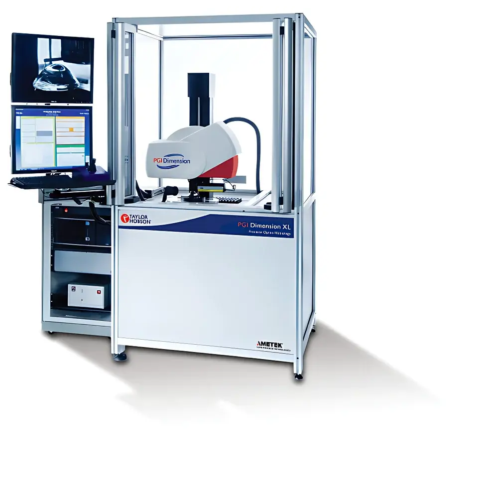
Taylor Hobson PGI Matrix High-Speed Fully Automatic Precision Optical Profilometer
| Brand | Taylor Hobson |
|---|---|
| Origin | United Kingdom |
| Model | PGI Matrix 1 / PGI Matrix 3 / PGI Matrix 5 |
| Type | Contact Profilometer / Surface Roughness Tester |
| Measurement Principle | Precision Stylus-Based Topographic Profiling with PGI (Precision Geometry Interferometry) Signal Processing |
| Software Platform | Form Talysurf Intra (v6.0+) with Advanced Aspheric Analysis Unit (AAU) |
| Compliance | ISO 25178-2, ISO 4287, ISO 11562, ISO 12780, ASTM E1158, USP <1058> (Analytical Instrument Qualification), FDA 21 CFR Part 11 (Audit Trail & Electronic Signatures Enabled) |
| Environmental Compensation | Real-time X-axis & radius thermal drift compensation algorithm |
| Key Output Metrics | Residual form error (sub-micron), aspheric deviation (nm-level), slope error (µrad), ring zone depth, diffraction step height reconstruction, reverse-coefficient fitting for aspheric/diffractive surfaces |
Overview
The Taylor Hobson PGI Matrix is a high-speed, fully automated contact profilometer engineered for precision geometric metrology of optical components—particularly spherical, aspheric, and diffractive surfaces—in both R&D laboratories and high-volume production environments. Unlike conventional stylus profilers, the PGI Matrix integrates proprietary Precision Geometry Interferometry (PGI) signal processing technology, enabling sub-micron residual form error reconstruction from raw topographic scans. This capability is critical for validating surface fidelity in ultra-precision optics used in lithography systems, laser resonators, AR/VR waveguides, and astronomical instrumentation. The system operates on a rigid granite base with motorized, programmable Z-stage and high-resolution linear encoders (0.1 nm resolution), ensuring traceable dimensional accuracy per ISO 10360-2 and ISO 14253-1. Its closed-loop servo-controlled positioning architecture supports repeatable tip approach, dwell, and retraction sequences essential for compliant roughness and form measurement under ISO 25178-2.
Key Features
- Fully automated measurement cycle—from part loading to report generation—enabled by programmable XYZ stage with integrated part recognition and auto-alignment routines.
- Patented PGI signal processing engine delivering nanometer-level residual shape error analysis, even across large-diameter (>300 mm) or high-slope (>15°) aspheric surfaces.
- Advanced Aspheric Analysis Unit (AAU) software module providing real-time computation of sag error, radius deviation, slope error (in µrad), ring zone depth, and diffraction step height decomposition.
- Reverse-coefficient fitting algorithm that reconstructs actual manufactured surface geometry—including manufacturing-induced deviations—and outputs Zernike or Q-type polynomial coefficients for design iteration feedback.
- Real-time thermal compensation: X-axis positional drift and best-fit radius recalibration algorithms automatically adjust for ambient temperature fluctuations during extended CNC-integrated operation.
- Modular configuration options (PGI Matrix 1, 3, and 5) differing in vertical range (±10 mm to ±50 mm), scan length (up to 300 mm), and probe force control granularity (0.1–50 mN), supporting scalability from lab prototyping to inline SPC deployment.
Sample Compatibility & Compliance
The PGI Matrix accommodates optical substrates ranging from fused silica and CaF₂ to chalcogenide glasses and diamond-turned aluminum mirrors. It accepts plano, spherical, toroidal, and freeform geometries up to Ø350 mm and 150 mm convex/concave radius of curvature. Probe tips include diamond (2 µm radius), sapphire (5 µm), and custom tungsten carbide variants optimized for soft coatings or high-aspect-ratio microstructures. All measurement protocols adhere to ISO 25178-2 (areal surface texture), ISO 4287 (profile roughness), and ISO 12780 (straightness and flatness). System qualification documentation supports IQ/OQ/PQ execution per GAMP 5 and satisfies audit requirements for ISO 9001, IATF 16949, and FDA-regulated optical device manufacturing (21 CFR Part 820).
Software & Data Management
Form Talysurf Intra v6.0+ serves as the unified platform, featuring a role-based user interface with configurable dashboards, multi-language support (EN/DE/FR/JP/CN), and embedded GLP/GMP-compliant data handling. Audit trails record all parameter changes, operator logins, calibration events, and report exports with time-stamped digital signatures. Raw profile data is stored in vendor-neutral .asc and .csv formats; full metrological metadata (environmental conditions, probe ID, calibration certificate traceability) is embedded in XML headers. Batch reporting tools generate ASME Y14.5-compliant GD&T summaries, statistical process control charts (X̄-R, Cpk), and automated pass/fail sorting indicators synchronized with factory MES via OPC UA or REST API.
Applications
- Validation of aspheric lens molds and finished injection-molded polymer optics for automotive LiDAR and smartphone camera modules.
- In-process verification of diamond-turned infrared optics (e.g., ZnSe, Ge) prior to thin-film coating.
- Root-cause analysis of mid-spatial-frequency errors (MSF) contributing to scatter in EUV lithography projection optics.
- Reverse engineering of legacy optical surfaces for digital twin reconstruction and tolerance stack-up simulation.
- Qualification of diffractive optical elements (DOEs) including kinoforms and multi-level etched structures, with layer-wise step height metrology.
- Supporting ISO 10110-5 compliance testing for surface imperfections and power error in precision telescope mirrors.
FAQ
What distinguishes PGI Matrix from standard contact profilometers?
It combines mechanical scanning stability with PGI signal processing to resolve residual form errors at sub-micron levels—beyond the capability of conventional filtering methods—while maintaining traceability to SI units.
Is the system compatible with ISO 21 CFR Part 11 requirements?
Yes. Form Talysurf Intra includes electronic signature workflows, immutable audit trails, and role-based access control validated for regulated environments.
Can it measure steep aspheric surfaces with slopes exceeding 20 degrees?
Yes—via adaptive probe angle adjustment and dynamic force control, supported by AAU’s slope error correction model.
How does thermal drift compensation function during long-duration measurements?
Embedded environmental sensors feed real-time temperature gradients into X-axis position and radius-of-curvature compensation algorithms, reducing recalibration frequency by up to 70% in uncontrolled shop-floor settings.
What level of training is required for operators?
Basic measurement tasks require under 2 hours of guided instruction; advanced AAU analysis and reverse-coefficient fitting are typically performed by metrology engineers with optical design familiarity.