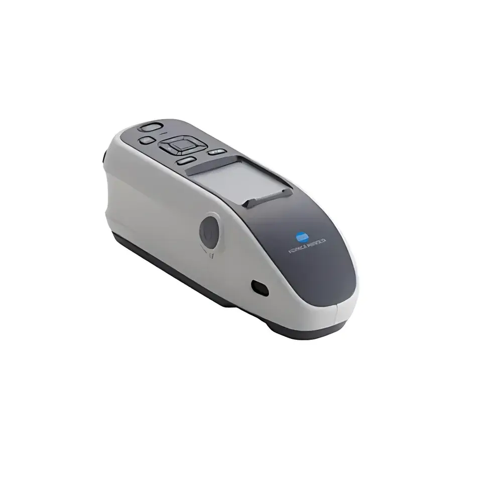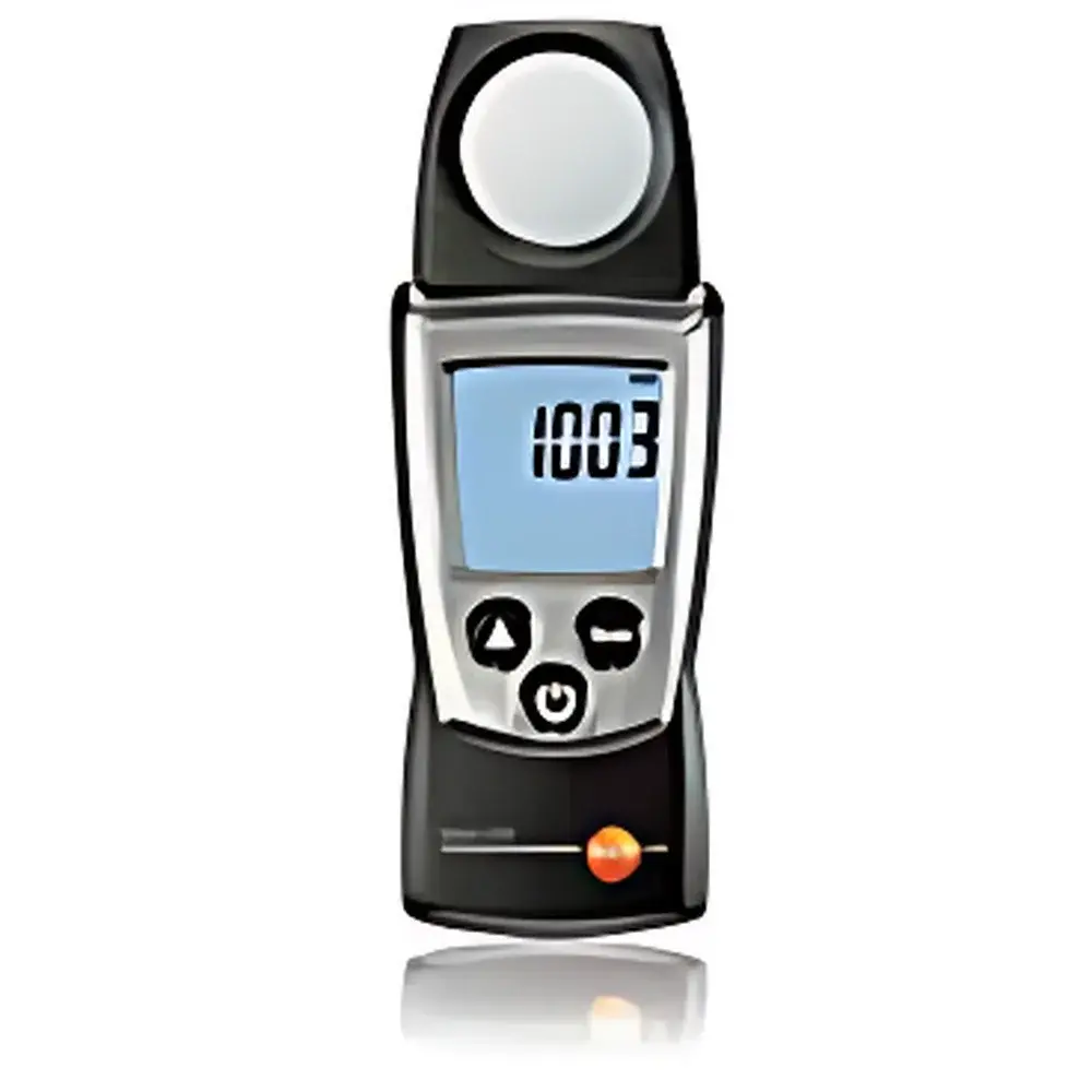
Testo 540 Digital Illuminance Meter
| Origin | Jiangsu, China |
|---|---|
| Manufacturer Type | Authorized Distributor |
| Origin Classification | Domestic (China) |
| Model | Testo 540 |
| Pricing | Available Upon Request |
| Sensor | Phototransistor |
| Measurement Range | 0–99,999 lux |
| Resolution | 1 lux (0–19,999 lux) |
| Accuracy | ±3% of reading (vs. traceable reference standard) |
| Sampling Rate | 0.5 s per measurement |
| Units | lux, foot-candles (fc) |
| Operating Temperature | 0–+50 °C |
| Power Supply | Two AAA alkaline batteries |
| Battery Life | Up to 200 hours (with backlight disabled, typical usage) |
| Ingress Protection | IP10 |
| Dimensions | 133 × 46 × 25 mm |
| Weight | 95 g |
Overview
The Testo 540 Digital Illuminance Meter is a compact, handheld photometric instrument engineered for precise and repeatable measurement of ambient illuminance in occupational, architectural, industrial, and educational environments. It operates on the principle of photopic spectral response—calibrated to match the CIE Standard Photometric Observer (V(λ) curve)—ensuring measurements reflect human visual sensitivity across the visible spectrum (380–780 nm). Unlike broadband radiometric sensors, the Testo 540 integrates a silicon phototransistor with optical filtering optimized for luminous flux quantification in photometric units (lux), making it suitable for compliance verification against lighting standards such as EN 12464-1 (Lighting of Workplaces), ISO/CIE 8995, and IESNA RP-1. Its real-time sampling rate of 0.5 seconds enables rapid assessment of dynamic lighting conditions, including flicker-prone LED installations and daylight-responsive control systems.
Key Features
- Photopic-response-optimized sensor aligned to CIE V(λ) spectral sensitivity curve for biologically relevant illuminance evaluation
- Auto-ranging digital display with dual-unit capability (lux and foot-candles), configurable via front-panel controls
- Hold function for freezing instantaneous readings—critical during single-operator field surveys or hard-to-access mounting positions
- Max/Min value tracking with timestamped memory recall, supporting trend analysis over extended measurement intervals
- Low-power architecture enabling up to 200 hours of continuous operation on two standard AAA alkaline cells
- Compact ergonomic housing (133 × 46 × 25 mm, 95 g) designed for one-handed use and integration into routine safety or facility audits
- IP10-rated enclosure—suitable for indoor dry environments; not intended for outdoor exposure or high-humidity locations without protective housing
Sample Compatibility & Compliance
The Testo 540 is validated for use with planar, diffuse, and directional light sources—including incandescent, fluorescent, HID, and modern solid-state lighting (LED, OLED). It meets fundamental metrological requirements for workplace lighting assessment per EN 12464-1:2021 Annex A (instrument classification Class L) and supports documentation workflows compliant with ISO/IEC 17025-accredited laboratories when used with traceable calibration certificates. While the device itself does not provide GLP/GMP audit trails or 21 CFR Part 11-compliant electronic records, its stable analog signal path and linear response enable integration into validated data acquisition systems when paired with external logging hardware and calibrated reference lamps (e.g., NIST-traceable tungsten halogen standards).
Software & Data Management
The Testo 540 operates as a standalone, button-driven instrument without Bluetooth, USB, or PC connectivity. All data handling is performed locally: measurements are displayed in real time, and max/min values persist until manually reset. For regulatory reporting or long-term monitoring, users typically transcribe values into spreadsheets or LIMS platforms. Optional accessories—including the Testo calibration service certificate (traceable to national standards) and protective soft case—support documented quality assurance practices. No proprietary software or firmware updates are required; the unit functions reliably across its full temperature range (0–+50 °C) without thermal drift compensation circuitry.
Applications
- Occupational health & safety inspections: verifying minimum illuminance levels at workstations, control rooms, and emergency egress pathways
- Building commissioning and retrofit validation: quantifying lighting uniformity, daylight harvesting efficiency, and post-installation energy savings
- Educational facility assessments: ensuring classroom and laboratory lighting meets national pedagogical guidelines (e.g., ANSI/IES RP-3-22)
- Museum and archival storage monitoring: tracking cumulative light exposure to prevent photochemical degradation of sensitive artifacts
- Industrial maintenance: diagnosing underperforming fixtures, identifying aging ballasts, and validating recalibration after lamp replacement
- Photobiological safety pre-screening: preliminary evaluation of UV-A and visible irradiance in proximity to unshielded light sources (supplemental to spectroradiometric analysis)
FAQ
What is the calibration interval recommendation for the Testo 540?
Testo recommends annual calibration against a traceable reference source; more frequent verification is advised in high-use or critical compliance settings.
Can the Testo 540 measure pulsed or modulated light sources accurately?
Due to its 0.5-second integration time, the device reports time-averaged illuminance and is not suitable for characterizing high-frequency flicker (>100 Hz) or PWM-dimmed LEDs without supplemental oscilloscopic validation.
Is the sensor cosine-corrected for off-axis incident light?
Yes—the diffuser design incorporates an approximated cosine angular response (f2 error < ±3% up to 75° incidence), conforming to CIE 69 and DIN 5032-7 requirements for general-purpose illuminance meters.
Does the Testo 540 comply with FDA or EU medical device regulations?
No—it is classified as a general-purpose industrial measurement tool and is not certified as a medical, in vitro diagnostic, or Class I/IIa device under MDR 2017/745 or 21 CFR Part 820.
How is battery replacement performed, and does it affect zero stability?
Batteries are accessed via a screwless sliding cover; no recalibration is required after replacement, as the circuit employs stable voltage regulation and auto-zeroing on power-up.