Triaxial Electromagnetic Vibration Shaker System
| Brand | Other Brands |
|---|---|
| Origin | Imported |
| Manufacturer Type | Authorized Distributor |
| Frequency Range | 1–600 Hz |
| Max. Load Capacity | 100 kg |
| Peak Acceleration | 20 g |
| Adjustable Peak-to-Peak Amplitude | 0–5 mm |
| Table Surface Dimensions (L×W) | 50 × 50 cm |
| Shaker Power Rating | 2.2 kW |
| Control Modes | Sine, Amplitude Modulation (AM), Fixed-Frequency Sine, Programmable Sweep, Logarithmic Sweep, Octave Sweep, Time-Controlled Operation |
| Communication Interface | RS-485 |
| Power Supply | 220 V ±20%, Max. Current: 10 A |
| Frequency Resolution | 0.01 Hz (display), Accuracy: ±0.1 Hz |
| Operating Axes | Vertical, Horizontal, or Combined Triaxial (X/Y/Z) |
Overview
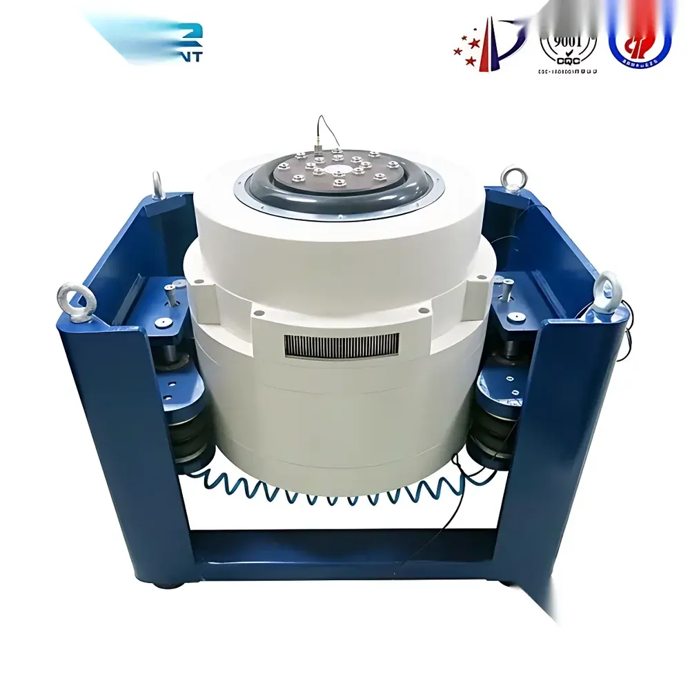
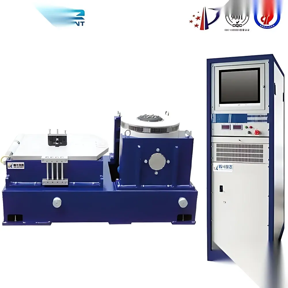
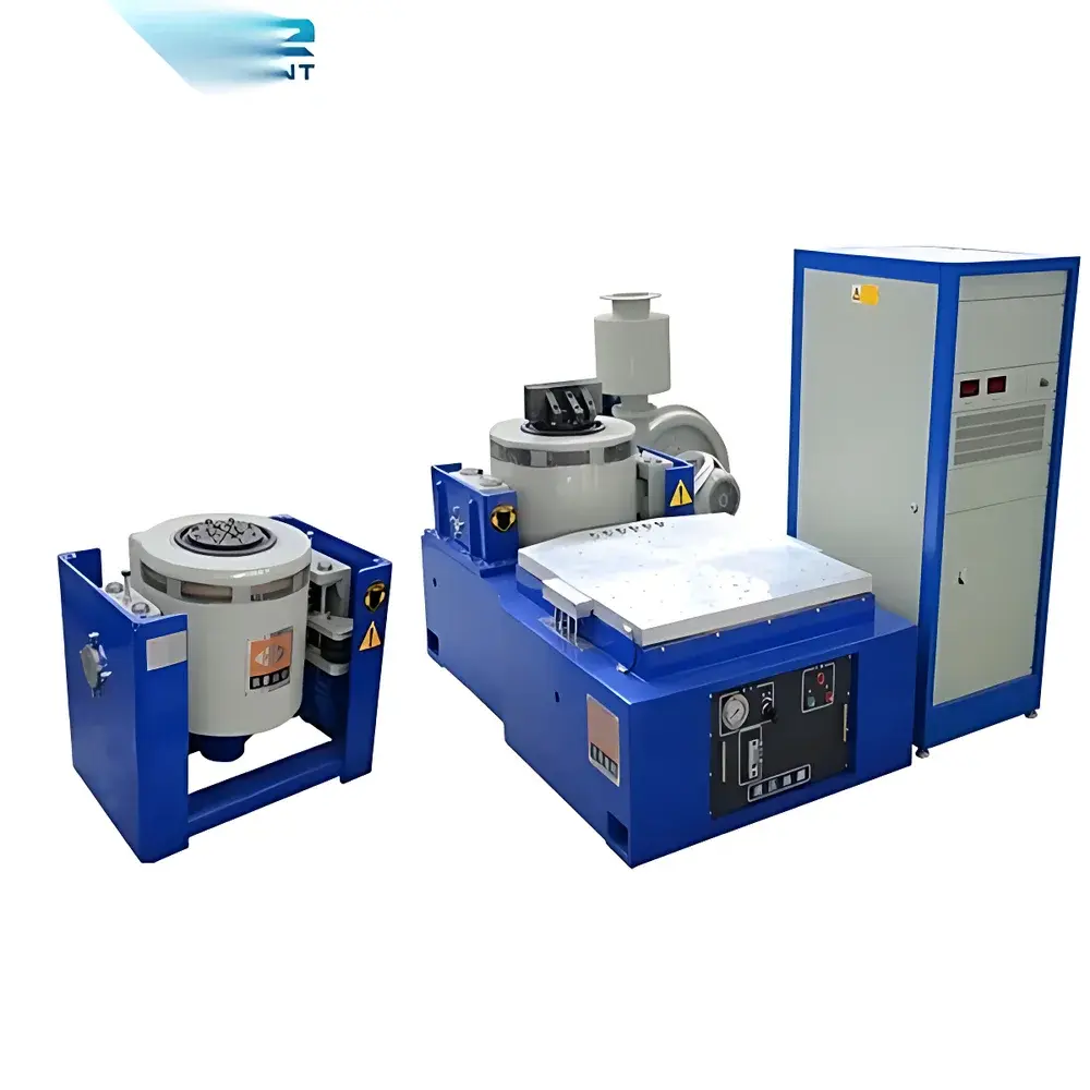
The Triaxial Electromagnetic Vibration Shaker System is a precision-engineered electrodynamic shaker platform designed for rigorous mechanical vibration testing of components, assemblies, and packaged goods under controlled dynamic loading conditions. Based on electromagnetic force generation principles—where a voice-coil actuator interacts with a permanent magnetic field to produce reproducible inertial forces—the system delivers high-fidelity sinusoidal, swept-sine, and programmable waveforms across three orthogonal axes (X, Y, Z). Its architecture supports both single-axis and simultaneous triaxial excitation, enabling realistic simulation of real-world transportation, operational, and environmental vibration profiles. The system complies with foundational test standards including ISO 10816 (mechanical vibration evaluation), IEC 60068-2-6 (vibration testing for electrotechnical products), and ASTM D999 (vibration testing of shipping containers), forming a core asset in reliability engineering, quality assurance, and product development laboratories.
Key Features
- Electrodynamic actuation with 2.2 kW amplifier driving capability, ensuring stable force output up to 20 g peak acceleration at loads ≤100 kg
- Wide frequency coverage from 1 Hz to 600 Hz, supporting low-frequency resonance detection and high-frequency fatigue assessment
- Adjustable peak-to-peak displacement range of 0–5 mm, dynamically constrained by the 20 g acceleration ceiling per ISO 5344 compliance limits
- Multi-mode excitation control: fixed-frequency sine, amplitude-modulated (AM) signals, linear/logarithmic sweeps, octave-based frequency stepping, and time-gated operation
- Programmable sequence engine supporting up to 15 user-defined segments per test profile, each configurable for frequency, dwell time, sweep rate, and direction (up/down/up-down)
- RS-485 digital interface for integration into automated test stands and SCADA environments; compatible with industry-standard controller protocols
- Rigid 50 × 50 cm aluminum alloy table surface with threaded mounting patterns (M6/M8), optimized for modal mass distribution and minimal parasitic resonance
- Real-time frequency display resolution of 0.01 Hz, calibrated accuracy ±0.1 Hz across full operating range
Sample Compatibility & Compliance
The shaker accommodates test specimens up to 100 kg mass with center-of-gravity height ≤30 cm above the table surface. Mounting fixtures, slip tables, and isolation platforms may be added for extended payload handling or multi-degree-of-freedom coupling. All mechanical interfaces adhere to ISO 13373-1 guidelines for vibration sensor placement and fixture design. The system supports GLP-compliant test execution when paired with validated data acquisition hardware and audit-trail-enabled software (e.g., compliant with FDA 21 CFR Part 11 requirements for electronic records). Test reports generated via optional PC-based control include timestamped waveform metadata, calibration traceability, and pass/fail criteria aligned with MIL-STD-810H Method 514.7 or GB/T 2423.10–2019.
Software & Data Management
While the base unit includes front-panel digital control, full functionality is unlocked via optional PC-based software (sold separately). This application provides real-time FFT spectrum analysis, waterfall plot generation, transmissibility mapping, and automated report export in PDF/CSV formats. Data logging supports ≥10 kHz sampling rates with 24-bit ADC resolution. Software architecture incorporates role-based access control, electronic signature workflows, and secure database archiving—enabling alignment with ISO/IEC 17025 accreditation requirements for testing laboratories. Calibration certificates are digitally embedded and version-controlled within the software environment.
Applications
- Structural durability validation of automotive ECUs, battery modules, and infotainment systems
- Package integrity assessment per ISTA 3A/3E protocols for e-commerce logistics
- Vibration-induced failure mode analysis (crack initiation, solder joint fatigue, connector fretting) in aerospace avionics
- Modal parameter identification (natural frequencies, damping ratios, mode shapes) using impact or shaker excitation
- Qualification testing of medical devices per IEC 60601-1 clause 9.4.2 (mechanical stress endurance)
- Environmental stress screening (ESS) in electronics manufacturing prior to burn-in
FAQ
What is the maximum allowable center-of-gravity height for a 100 kg test specimen?
For optimal dynamic response and safety, the center of gravity should not exceed 30 cm above the table surface. Higher CG configurations require custom fixture analysis and may necessitate reduced acceleration limits.
Does the system support closed-loop control with accelerometer feedback?
Yes—when equipped with optional charge-mode accelerometers and a compatible signal conditioner, the system supports real-time acceleration-controlled closed-loop operation per ISO 10816-3 Annex C.
Is calibration traceable to national metrology institutes?
Factory calibration is performed against NIST-traceable reference standards; full calibration certificates—including sensitivity, linearity, and phase response data—are provided upon request.
Can the shaker operate continuously at 600 Hz and 20 g?
Continuous operation at maximum specification points is thermally limited; duty cycles must comply with manufacturer thermal derating curves, typically requiring ≥15-minute cooldown intervals after 30 minutes of peak-load operation.
What documentation is included for regulatory submissions?
Standard delivery includes installation qualification (IQ), operational qualification (OQ) templates, and a system configuration record—fully editable for GMP/GLP audit readiness.
Related Products
")


