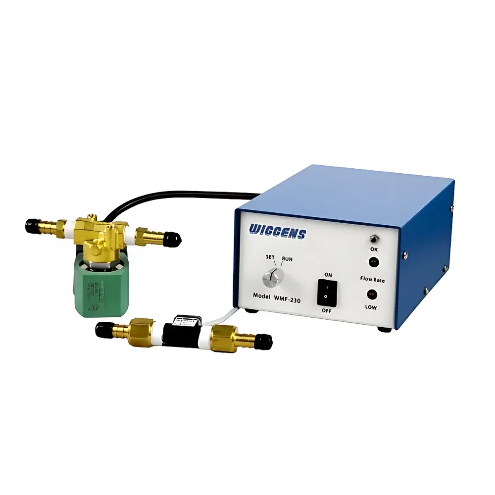
WIGGENS WFM Series Water Flow Monitor and Safety Cut-off System
| Brand | WIGGENS |
|---|---|
| Origin | Germany |
| Model | WFM |
| Dimensions | 63.5 mm (H) × 95.0 mm (W) × 138.0 mm (D) |
| Input Voltage | 230 V AC |
| Max Load Capacity | 2300 W |
| Flow Sensor Options | WFM-01 (0.1–2.5 L/min), WFM-02 (1–10 L/min), WFM-03 (2–30 L/min) |
| Shut-off Valve | 250MV Solenoid Valve |
| Audible Alarm | WFM-AA, 70 dB |
| Digital Alarm Output | WFM-OC, 170 mA current signal |
Overview
The WIGGENS WFM Series Water Flow Monitor and Safety Cut-off System is an engineered safety interface designed for integration into laboratory thermal management infrastructure—specifically condensers, recirculating chillers, water baths, and heating mantles requiring continuous coolant circulation. Operating on the principle of real-time volumetric flow rate detection via calibrated turbine-based or Hall-effect flow sensors, the WFM continuously measures coolant throughput and compares it against a user-defined threshold. Upon detecting flow deviation below the setpoint—caused by pump failure, tubing rupture, fitting disconnection, or filter clogging—the system initiates a dual-layer safety response: (1) immediate de-energization of the connected heating or cooling load (up to 2300 W at 230 V AC), and (2) actuation of the 250MV solenoid shut-off valve to terminate primary coolant supply (tap water or chiller output). This fail-safe architecture prevents thermal runaway, equipment overheating, and uncontrolled fluid discharge—critical for compliance with laboratory risk mitigation protocols under ISO/IEC 17025 and GLP frameworks.
Key Features
- Modular sensor compatibility: Supports three interchangeable flow sensor models—WFM-01 (0.1–2.5 L/min), WFM-02 (1–10 L/min), and WFM-03 (2–30 L/min)—enabling precise range selection based on system hydraulics and application requirements.
- Dual-action safety interlock: Simultaneous power cutoff to downstream equipment and mechanical isolation of coolant supply via fast-response 250MV solenoid valve (response time < 1.5 s).
- Configurable alarm signaling: Integrated WFM-AA audible alarm (70 dB) provides local acoustic notification; optional WFM-OC digital output module delivers a 170 mA current signal for remote SCADA or building management system (BMS) integration.
- Compact industrial enclosure: Ruggedized housing (63.5 × 95.0 × 138.0 mm) with IP54-rated ingress protection ensures reliable operation in typical laboratory environments with moderate humidity and particulate exposure.
- No software dependency: Fully hardware-based logic control eliminates firmware updates, cybersecurity vulnerabilities, or calibration drift associated with embedded microprocessors—enhancing long-term operational integrity.
Sample Compatibility & Compliance
The WFM system is compatible with aqueous coolants including deionized water, glycol-water mixtures (up to 50% v/v), and tap water within standard municipal specifications. It is not intended for use with aggressive solvents, oils, or high-viscosity fluids. All components comply with EU RoHS Directive 2011/65/EU and CE marking requirements for low-voltage equipment (LVD 2014/35/EU). The 230 V AC input configuration meets EN 61000-6-3 (EMC emission) and EN 61000-6-2 (immunity) standards. While the device itself does not carry UL or CSA certification, its relay output and valve interface are rated for use in Class I, Division 2 hazardous locations when installed per NEC Article 500 guidelines.
Software & Data Management
The WFM operates as a standalone analog-electronic safety controller with no onboard data logging, network connectivity, or proprietary software interface. Flow threshold setting is performed manually via front-panel potentiometer; status indication is provided via LED (green = normal flow, red = alarm state). For laboratories requiring audit trails or electronic record retention, the WFM-OC digital alarm output can be interfaced with third-party PLCs or data acquisition systems supporting 4–20 mA or discrete current-loop inputs—enabling timestamped event capture aligned with FDA 21 CFR Part 11-compliant electronic records when deployed within validated workflows.
Applications
- Protection of rotary evaporators during solvent distillation where condenser cooling failure may lead to vapor escape or bumping.
- Safeguarding of high-power heating circulators used in reaction calorimetry or polymer synthesis setups.
- Integration into HVAC-assisted fume hood cooling loops to prevent localized overheating of duct-mounted heat exchangers.
- Preventive monitoring of chilled mirror hygrometers and dew point analyzers reliant on stable coolant flow for thermal stabilization.
- Redundant flow verification in GMP-compliant bioreactor jacket cooling circuits where single-point failure modes must be mitigated.
FAQ
Does the WFM require periodic recalibration?
No. The WFM uses factory-calibrated mechanical flow sensors with no field-adjustable gain or zero offset. Calibration certificates are supplied with each WFM-01/02/03 sensor unit and remain valid for the lifetime of the component under normal operating conditions.
Can multiple WFM units be daisy-chained for centralized monitoring?
Not natively. Each WFM operates independently. However, the WFM-OC alarm output can be wired in series to a common alarm bus, enabling collective fault indication across multiple units using external relay logic.
Is the 250MV shut-off valve compatible with deionized water systems?
Yes. The 250MV valve features EPDM seals and stainless steel wetted parts, making it suitable for DI water service up to 40 °C and pH 5–9. Avoid prolonged exposure to chlorine concentrations exceeding 1 ppm.
What is the minimum recommended upstream straight-pipe length for accurate flow measurement?
For laminar flow stability, install ≥10× pipe diameter of straight tubing upstream of the WFM-01/02/03 sensor inlet. Avoid installing immediately after elbows, tees, or valves without adequate flow conditioning.
Can the WFM be used with variable-frequency drive (VFD) controlled pumps?
Yes—provided the pump’s flow output remains within the selected sensor’s linear range and exhibits minimal pulsation. For highly pulsatile VFD outputs, consider adding a flow dampener upstream of the sensor to ensure stable signal interpretation.


