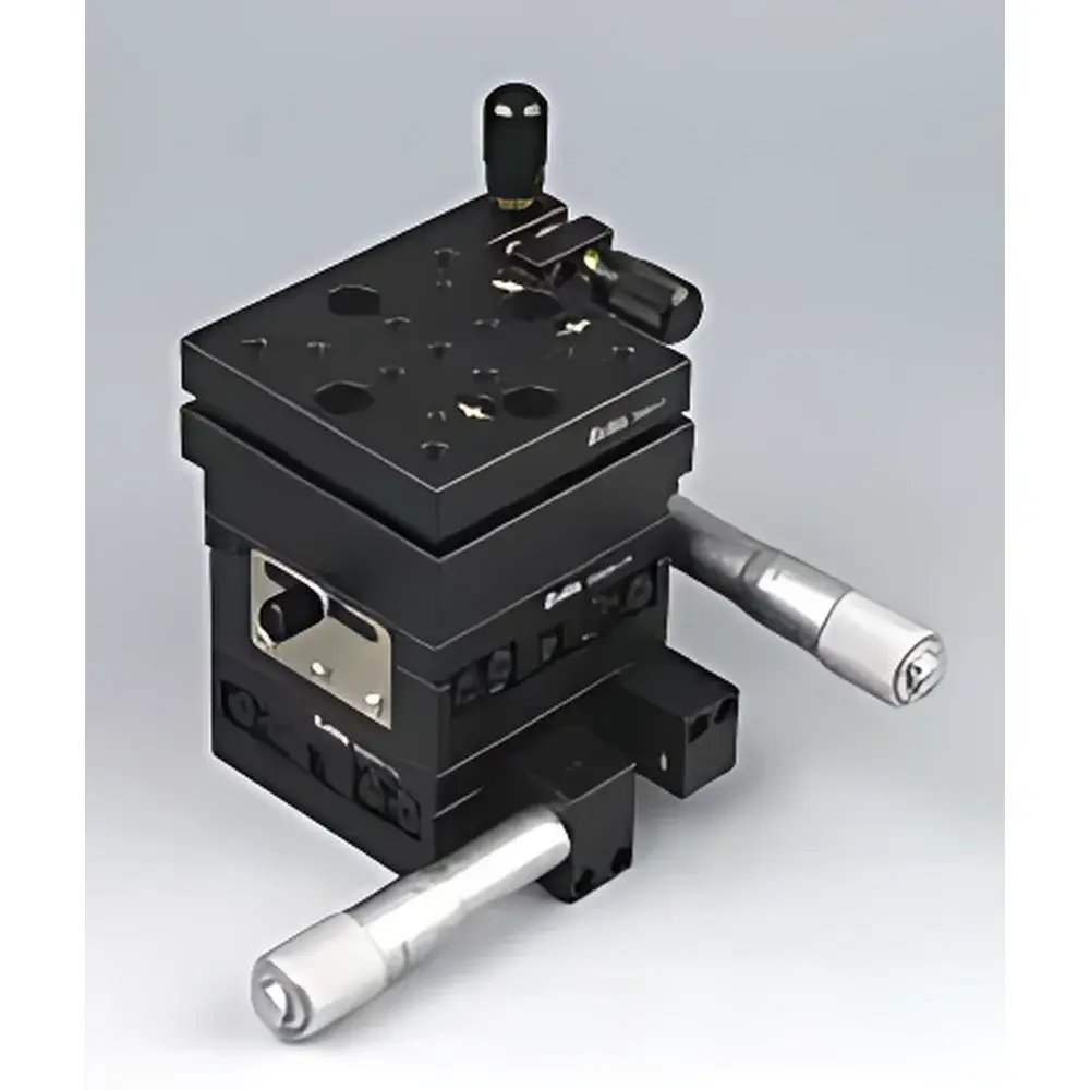
ZOLIX ASM25XY-T4 Four-Axis Combined Translation and Tip-Tilt Stage
| Brand | ZOLIX |
|---|---|
| Origin | Beijing, China |
| Manufacturer Type | Direct Manufacturer |
| Country of Origin | China |
| Model | ASM25XY-T4 |
| Pricing | Available Upon Request |
| Motion Axes | X, Y, θx (pitch), θz (yaw) |
| Linear Travel | ±25 mm (X and Y) |
| Angular Range | ±4° (θx), ±2.5° (θz) |
| Core Subassemblies | Two ASM25-1A Linear Translation Stages, Two TSMT-4 Precision Tip-Tilt Rotation Stages, One BP-25 Mounting Adapter Plate |
Overview
The ZOLIX ASM25XY-T4 Four-Axis Combined Translation and Tip-Tilt Stage is an integrated optomechanical positioning system engineered for high-stability alignment tasks in precision optical laboratories. Designed around a modular architecture, it combines orthogonal linear displacement (X and Y) with independent rotational degrees of freedom about two non-collinear axes (θx — pitch, and θz — yaw), enabling full 4D spatial control of optical components such as mirrors, lenses, fiber couplers, or detectors. Its operation relies on manual micrometer-driven adjustment with kinematic coupling between subassemblies, ensuring minimal crosstalk and repeatable positioning under static loading conditions. The stage is optimized for applications requiring iterative beam steering, collimation fine-tuning, interferometric path balancing, and multi-axis alignment of free-space optical trains—particularly where compact footprint and mechanical rigidity are critical.
Key Features
- Four independent, decoupled motion axes: X and Y linear translation (±25 mm each), plus pitch (θx: ±4°) and yaw (θz: ±2.5°) rotation—enabling full orientation + position correction without external goniometers.
- Modular construction using ZOLIX’s proven OEM-grade components: two ASM25-1A high-rigidity linear translation stages (25 mm travel, M6 mounting holes, 0.005 mm resolution via differential micrometers), two TSMT-4 low-backlash tip-tilt rotation stages (±4°/±2.5° range, <5 arcsec repeatability, preloaded angular bearings), and a BP-25 rigid aluminum adapter plate with precision-machined alignment dowels.
- Integrated baseplate design ensures co-planar mounting surfaces and minimized parasitic motion; all adjustment screws feature knurled brass knobs with locking thumbscrews for stable hold during vibration-prone environments.
- Black-anodized 6061-T6 aluminum housing provides thermal stability (CTE ≈ 23.6 µm/m·K), corrosion resistance, and ESD-safe grounding compatibility—critical for cleanroom and laser lab deployments.
- No motorization or electronics included; designed for manual operation in alignment-critical setups where tactile feedback and zero electromagnetic interference are required.
Sample Compatibility & Compliance
The ASM25XY-T4 accommodates optical elements up to Ø50 mm or 50 × 50 mm square footprints, with a maximum payload capacity of 1.2 kg uniformly distributed. Mounting is standardized to M4 and M6 threaded holes per ISO 8137-1 (optomechanical interface specification), supporting direct integration with cage systems (e.g., Thorlabs 30 mm or 60 mm), lens tubes, and custom optical breadboards. While not certified to ISO 9001 or CE for industrial automation use, the stage complies with general laboratory safety standards for manually operated mechanical devices (IEC 61000-6-2/6-3 immunity/emission limits apply only when used with optional motorized actuators). It is routinely deployed in university optics labs, R&D photonics facilities, and metrology calibration workflows adhering to ISO/IEC 17025 documentation requirements.
Software & Data Management
As a purely manual mechanical stage, the ASM25XY-T4 does not incorporate embedded firmware, digital encoders, or native software drivers. Position data must be recorded externally using calibrated dial indicators, laser interferometers (e.g., Keysight 5530 series), or vision-based alignment systems (e.g., IDS Imaging uEye cameras with OpenCV-based centroid tracking). For traceable alignment logs, users commonly integrate stage settings into LabVIEW or Python-controlled experiment protocols via external encoders mounted on micrometer shafts. Audit trails for positional configurations may be maintained in accordance with GLP principles when used in regulated optical testing environments—though no built-in 21 CFR Part 11 electronic signature functionality is provided.
Applications
- Laser cavity alignment: Precise angular registration of HR and OC mirrors while maintaining longitudinal cavity length.
- Fiber-to-free-space coupling optimization: Simultaneous correction of lateral offset (X/Y) and angular misalignment (θx/θz) to maximize coupling efficiency into single-mode fibers.
- Interferometer path balancing: Fine adjustment of reference and measurement arm mirrors in Michelson, Mach-Zehnder, or Twyman-Green configurations.
- Optical coherence tomography (OCT) sample arm calibration: Coordinated translation and tilt to maintain focus and minimize aberration across scanning volumes.
- Alignment of diffractive optical elements (DOEs) and micro-optic arrays where facet-level angular registration directly impacts diffraction efficiency.
FAQ
Is the ASM25XY-T4 compatible with vacuum environments?
No—standard version uses lubricated brass-on-steel micrometer threads and elastomeric locking components unsuitable for UHV or HV conditions. Vacuum-compatible variants require dry-film lubricants, stainless steel hardware, and vented micrometer housings (custom order only).
Can I add motorized actuators to this stage?
Yes—ZOLIX offers optional stepper motor kits (e.g., SM25-1A-M and TSMT-4-M) with NEMA 11 mounts and encoder feedback; integration requires mechanical modification and external motion controller (e.g., Newport ESP300 or Zaber T-NA).
What is the typical bidirectional repeatability for angular axes?
Under controlled lab conditions (23 ±1°C, no load), θx achieves ≤ ±8 arcsec and θz ≤ ±5 arcsec over repeated 1° excursions, verified using autocollimator measurements per ISO 230-2 Annex B.
Does the BP-25 adapter plate include kinematic mounting features?
No—it provides rigid, flat mounting with three precision-ground contact points but lacks ball-and-cone or flexure-based kinematic constraints; users requiring true kinematic mounting should add separate kinematic base adapters.