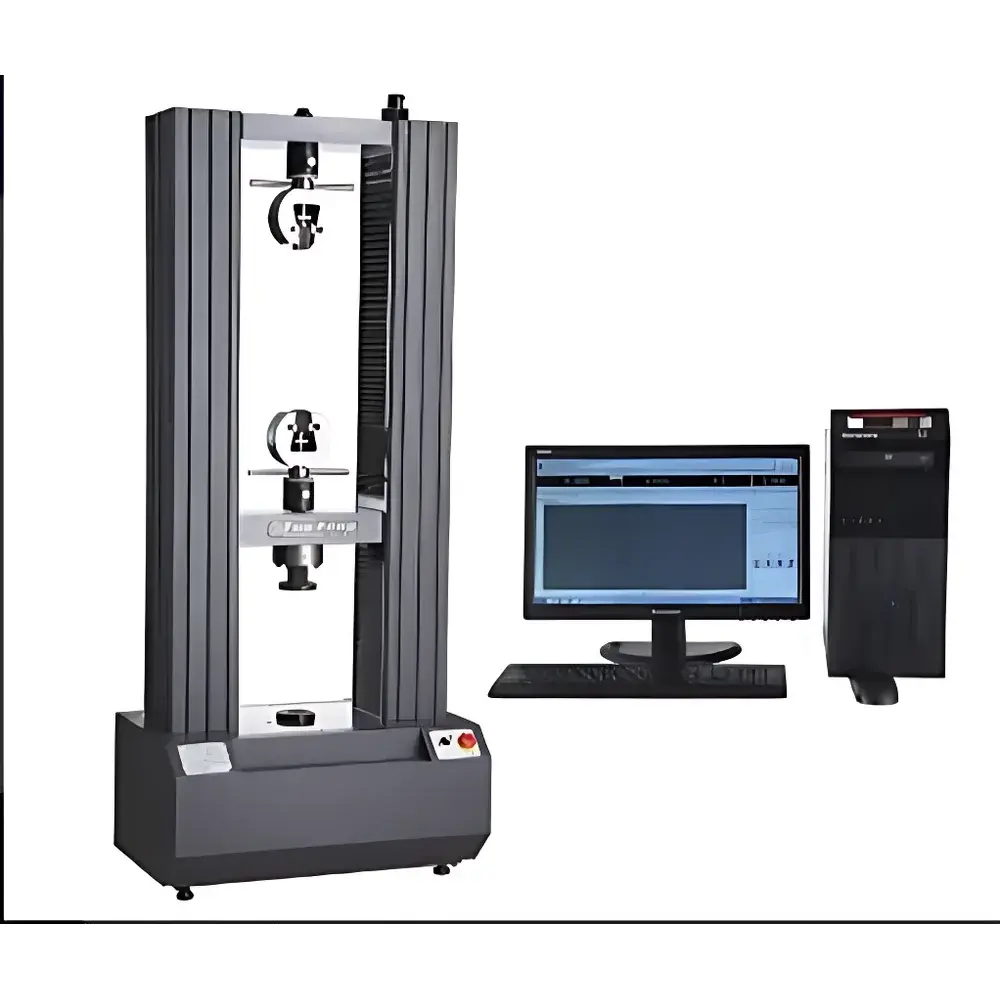
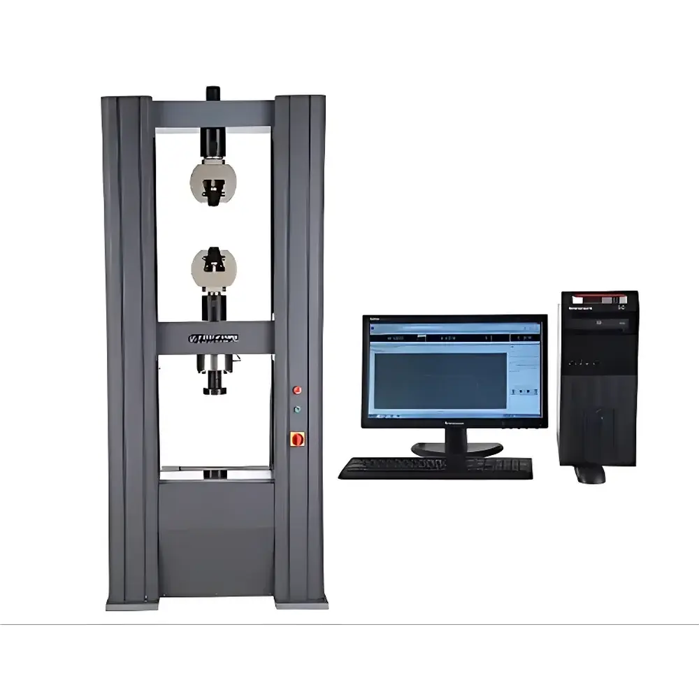
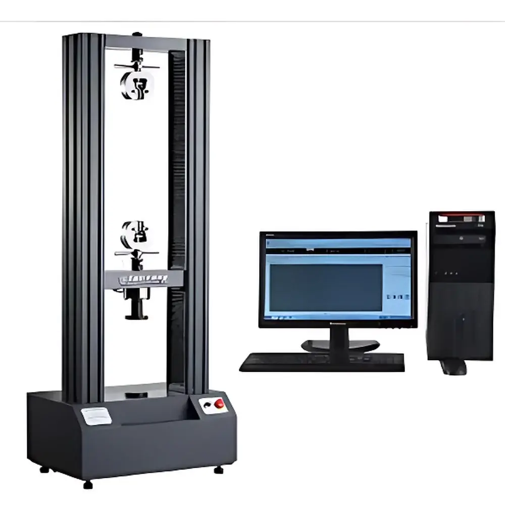
Tuofeng TFW-61S Photovoltaic Solder Ribbon Tensile Testing Machine
| Brand | Tuofeng |
|---|---|
| Origin | Shanghai, China |
| Manufacturer Type | Direct Manufacturer |
| Instrument Type | Electromechanical Tensile Testing Machine |
| Model | TFW-61S |
| Max Test Load | 100 kN |
| Force Measurement Range | 1 kg to 200 kN (0.2%–100% FS) |
| Force Accuracy | ±0.5% of reading |
| Crosshead Travel | 1000 mm |
| Displacement Resolution | 0.001 mm |
| Control System | PC-based with Windows-compatible software |
| Compliance | GB/T 16491–2008, JJG 475–2008, ASTM E4, ISO 7500-1, DIN 51221 |
Overview
The Tuofeng TFW-61S Photovoltaic Solder Ribbon Tensile Testing Machine is a high-precision electromechanical universal testing system engineered specifically for mechanical characterization of photovoltaic interconnect materials—particularly tin-coated copper solder ribbons used in solar cell module assembly. It operates on the principle of controlled uniaxial force application via a servo-driven ball-screw actuation system, enabling precise measurement of tensile strength, yield point, elongation at break, modulus of elasticity, and load-displacement behavior under standardized loading conditions. Designed to meet the stringent repeatability and traceability requirements of PV manufacturing quality control labs and R&D centers, the TFW-61S delivers consistent force resolution across its full 100 kN capacity range while maintaining structural rigidity and thermal stability during extended test cycles.
Key Features
- High-stiffness dual-column frame with reinforced base and crosshead, minimizing deflection during high-load tests up to 100 kN
- Precision ground ball-screw transmission system coupled with imported servo motor and planetary gearbox for smooth, low-noise motion control
- Force transducer calibrated to ISO 7500-1 Class 0.5 accuracy, with verified linearity and hysteresis < ±0.5% of full scale
- Optical encoder-based displacement measurement system offering 0.001 mm resolution and ±0.005% accuracy relative to reading
- Dual-speed automatic crosshead positioning (fast jog + fine adjustment) with programmable return-to-start functionality
- Integrated safety architecture including electronic limit switches, emergency stop circuitry, overload protection (>110% FS), and real-time hardware interlock monitoring
- Modular fixture interface supporting quick-change configurations for ribbon tensile grips, peel fixtures, and custom PV module interconnect jigs
Sample Compatibility & Compliance
The TFW-61S accommodates standard PV solder ribbons (flat or tinned rectangular cross-sections, typically 1–3 mm wide × 0.1–0.3 mm thick), as well as auxiliary samples including busbars, tabbing wires, and laminated cell-string assemblies. Its effective test width of 400 mm (expandable to 600 mm) and 1000 mm travel allow evaluation of both short-length ribbon segments and full-length interconnect strips under realistic boundary conditions. The system complies with international standards governing mechanical testing of metallic and composite conductors—including ASTM E8/E8M (tension tests of metallic materials), IEC 61215-2 (photovoltaic module qualification), UL 1703 Annex D (solder bond strength), and GB/T 25975–2018 (test methods for PV interconnection materials). All calibration and verification procedures align with ISO/IEC 17025 requirements for accredited testing laboratories.
Software & Data Management
The embedded Windows-based testing software supports GLP-compliant operation with full audit trail logging, user access levels (admin/operator), and electronic signature capability per FDA 21 CFR Part 11 guidelines. It enables multiple control modes—constant rate of extension (CRE), constant load hold, strain-controlled ramping, and displacement-limited cycling—with real-time plotting of force–displacement, stress–strain, and time-series curves. Data export is available in CSV, Excel, and PDF formats; curve overlays support comparative analysis across batches or material lots. Software modules include automated calculation of tensile strength (MPa), elongation (%), Young’s modulus (GPa), and solder joint shear resistance based on user-input geometry parameters. Firmware and application updates are provided free of charge throughout the instrument’s service life.
Applications
- Quantitative assessment of solder ribbon tensile strength and ductility prior to module lamination
- Evaluation of interfacial adhesion between tin coating and copper substrate under thermal cycling stress
- Comparative testing of alternative solder alloys (e.g., Pb-free SnAgCu vs. traditional SnPb) for mechanical reliability
- Validation of ribbon crimping, welding, or ultrasonic bonding processes in PV stringing lines
- Failure mode analysis of ribbon fractures occurring during module bending or hail impact simulation
- Supporting root-cause investigations in field failure analysis and warranty claim verification
FAQ
Does the TFW-61S support automated test sequence execution for batch testing?
Yes—the software allows creation and scheduling of multi-step test protocols with configurable pass/fail criteria, automatic data tagging, and report generation per sample ID.
Can the system be integrated into a factory MES or LIMS environment?
Yes—via optional OPC UA or Modbus TCP interface modules for bidirectional communication with enterprise systems.
Is third-party calibration certification available upon delivery?
Yes—certified calibration reports traceable to NIM (China National Institute of Metrology) or UKAS-accredited labs can be supplied upon request.
What is the recommended maintenance interval for the force sensor and drive system?
Annual verification of force transducer linearity and encoder calibration is advised; preventive maintenance of the servo drive and ball screw is scheduled every 12 months or after 5,000 test cycles.
Are custom grips for non-standard ribbon geometries available?
Yes—Tuofeng offers OEM-designed pneumatic, wedge-action, and self-aligning grips tailored to specific ribbon thickness, width, and surface finish requirements.


