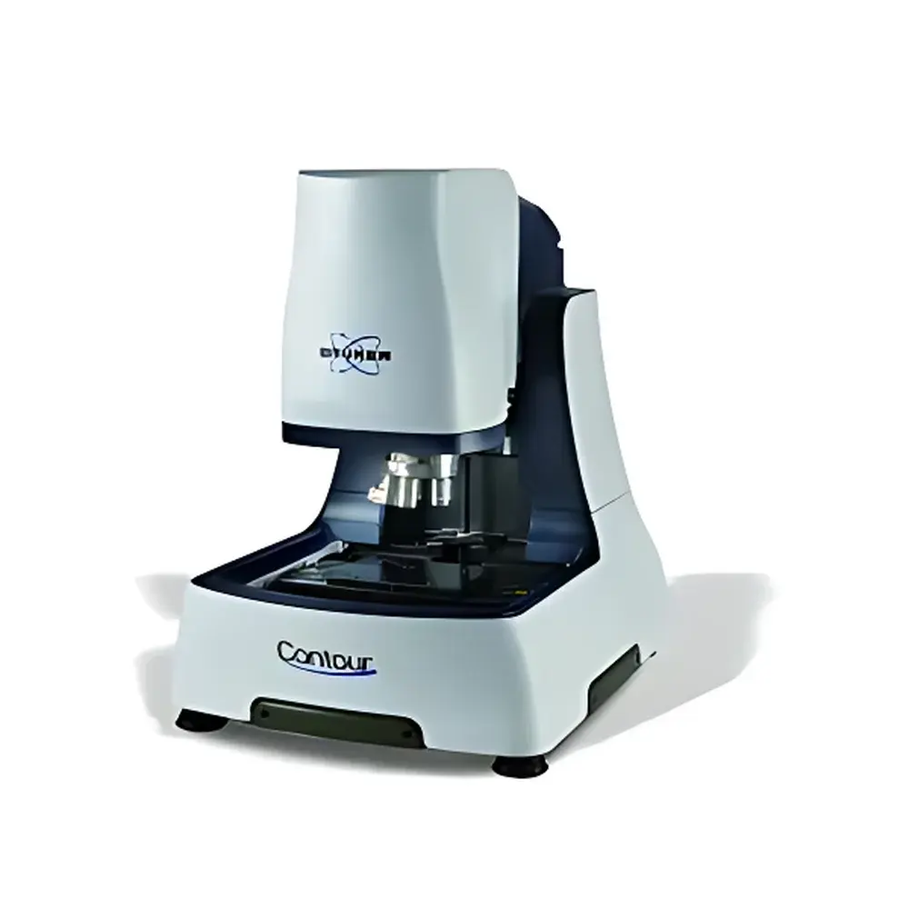
Bruker ContourX-500 3D Optical Profilometer
| Brand | Bruker |
|---|---|
| Origin | USA |
| Manufacturer Type | Authorized Distributor |
| Product Category | Imported |
| Model | ContourX-500 |
| Pricing | Upon Request |
| Instrument Type | Non-contact Profilometer / Surface Roughness Analyzer |
| Operating Principle | White Light Interferometry (WLI) |
| Compliance Standards | ISO 25178, ASME B46.1, ISO 4287 |
| Key Features | Encoder-equipped XY stage, motorized auto-tilting optical head, auto-brightness adjustment, USI universal scanning mode, pneumatic vibration isolation base, magnification-independent Z-resolution |
Overview
The Bruker ContourX-500 is a benchtop, fully automated 3D optical profilometer engineered for high-precision, non-contact surface topography measurement. Utilizing white light interferometry (WLI), the system delivers sub-nanometer vertical resolution and exceptional repeatability across a wide range of surface types—from ultra-smooth optics and silicon wafers to structured MEMS devices and textured biomedical implants. Unlike stylus-based profilers, WLI avoids mechanical contact, eliminating tip wear, surface damage, or deformation artifacts—critical for fragile, soft, or coated samples. The ContourX-500 integrates Bruker’s proprietary auto-tilting optical head, enabling programmable angular alignment during acquisition to minimize shadowing and maximize fringe contrast on inclined or curved surfaces. Its compact footprint—optimized with an integrated pneumatic isolation platform—retains the metrological performance of Bruker’s larger floor-standing WLI systems while fitting seamlessly into space-constrained cleanrooms, QC labs, and R&D environments.
Key Features
- Auto-tilting optical head with programmable angular range (±6°) for optimized fringe acquisition on sloped or freeform surfaces
- Encoder-based high-accuracy XY translation stage (50 mm × 50 mm travel) with closed-loop positioning and sub-micron repeatability
- Universal Scanning Interferometry (USI) mode: dynamically selects optimal scan strategy (vertical scanning, phase-shifting, or hybrid) based on surface slope, roughness, and reflectivity
- Magnification-independent Z-axis resolution: maintains consistent <0.1 nm vertical resolution regardless of objective magnification (from 2.5× to 100×)
- Real-time auto-brightness control and focus-assist algorithms for robust operation across heterogeneous samples
- Integrated pneumatic isolation base with active damping—no external vibration table required
- Modular objective turret supporting standard Mitutoyo, Nikon, and Olympus objectives (including long-working-distance and UV-enhanced variants)
Sample Compatibility & Compliance
The ContourX-500 accommodates diverse sample geometries and materials without contact-induced artifacts: polished mirrors, patterned wafers, microfluidic channels, laser-scribed solar cells, ophthalmic lenses, stent coatings, and polymer microstructures. It supports wafer sizes up to 200 mm diameter and accommodates heights up to 150 mm with optional extended-Z accessories. All surface texture and areal parameters—including Sa, Sq, Sz, Sdr, and functional indices (Sk, Spk, Svk)—are computed in strict accordance with ISO 25178-2:2012 and ISO 25178-601:2013. Roughness profile parameters (Ra, Rz, Rq) comply with ISO 4287 and ASME B46.1. Data traceability meets GLP/GMP requirements through audit-ready metadata logging, user access controls, and electronic signature support aligned with FDA 21 CFR Part 11 when configured with Bruker’s optional compliance software package.
Software & Data Management
Bruker’s Vision64 software provides a unified interface for acquisition, analysis, reporting, and automation. The platform supports script-driven batch processing via Python API integration, enabling custom workflows for production metrology (e.g., pass/fail criteria per site, statistical process control charting). Measurement reports are exportable in PDF, CSV, and industry-standard STEP AP210 formats. Raw interferograms and height maps are stored in Bruker’s native .ZDF format—a binary, metadata-rich container compliant with ASTM E2912-13 for digital surface data exchange. Version-controlled method files include full instrument configuration, filter settings, and calibration references, ensuring inter-laboratory reproducibility and regulatory readiness.
Applications
- Semiconductor manufacturing: post-CMP step height verification, trench depth profiling, lithographic resist characterization
- MEMS/NEMS development: actuator displacement mapping, diaphragm deflection analysis under pressure/voltage stimuli
- Ophthalmic device R&D: aspheric lens surface fidelity assessment, anti-reflective coating uniformity quantification
- Medical device QA: stent strut edge radius measurement, porous scaffold pore size distribution analysis
- Advanced optics: scratch/dig evaluation, polishing artifact identification, thin-film thickness mapping via multi-wavelength WLI
- Automotive tribology: bearing surface texturing validation, piston ring coating roughness certification
FAQ
What is the minimum resolvable feature size in lateral dimensions?
Lateral resolution is determined by the objective’s diffraction limit and ranges from ~0.35 µm (with 100× objective) to ~1.8 µm (with 2.5× objective), following the Rayleigh criterion.
Can the ContourX-500 measure transparent or semi-transparent thin films?
Yes—via spectral reflectance modeling in Vision64, it supports quantitative film thickness measurement on substrates such as SiO₂ on Si, photoresist on glass, or polymer layers on metal.
Is calibration traceable to NIST standards?
All Z-axis calibration artifacts are certified to NIST-traceable standards; Bruker provides factory calibration certificates with uncertainty budgets per ISO/IEC 17025 guidelines.
Does the system support automated multi-site measurement on wafers or PCBs?
Yes—using Vision64’s wafer map module, users define die-level coordinate systems, apply pattern recognition, and execute unattended multi-point acquisition with dynamic focus recovery.
How is thermal drift compensated during long-duration scans?
The system employs real-time thermal drift correction using embedded reference interferometers and ambient temperature monitoring, maintaining Z-stability within ±0.3 nm over 2-hour acquisitions.