CactuX Thermal BOX In-Situ Temperature-Controlled Stage for Micro-CT
| Brand | CactuX |
|---|---|
| Origin | Czech Republic |
| Model | Thermal BOX |
| Temperature Range | –30 °C to +60 °C |
| Accuracy | ±1 °C |
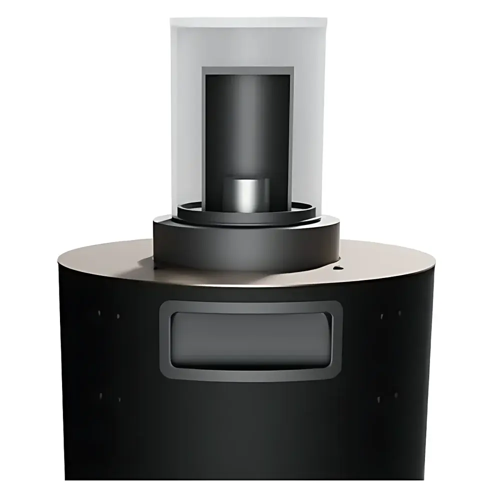
| Sample Chamber | Ø65 × 35 mm (customizable) |
| Dimensions (stage only) | 200 × 200 × 405 mm |
| Weight (stage only) | 4.25 kg |
| Power Supply | 230 V AC |
Overview
The CactuX Thermal BOX is an in-situ temperature-controlled stage engineered specifically for high-resolution X-ray micro-computed tomography (µCT) systems. It enables real-time, non-destructive observation of internal structural evolution in materials under dynamically controlled thermal conditions—ranging from –30 °C to +60 °C—during full 360° rotational scanning. Unlike conventional ex-situ thermal analysis, the Thermal BOX integrates directly into the CT gantry workflow, maintaining precise thermal boundary conditions while preserving geometric fidelity and reconstruction accuracy. Its design adheres to the physical constraints of microfocus X-ray sources and high-magnification detector geometries, minimizing beam attenuation and scatter through low-Z, CT-transparent construction (primarily aluminum alloys and specialized polymer composites). The system operates on a closed-loop Peltier-based thermoelectric control architecture, delivering bidirectional heating and cooling without external cryogens or compressed gas infrastructure—making it suitable for integration into shared laboratory environments, cleanrooms, and GLP-compliant imaging facilities.
Key Features
- Wide operational temperature range: –30 °C to +60 °C, with stability maintained at ±1 °C across the full span
- Programmable thermal ramping profiles—including isothermal holds, linear ramps, and stepwise cycling—configured via intuitive graphical interface
- Compact form factor (200 × 200 × 405 mm) optimized for compatibility with commercial µCT platforms (e.g., Zeiss Xradia, Bruker SkyScan, Thermo Fisher HeliScan), including clearance for rotation stages and collimator paths
- Modular sample holder system: Standard Ø65 × 35 mm cylindrical chamber; custom geometries (e.g., rectangular, extended height, or multi-sample trays) available upon request
- External control architecture: All electronics—including PID controller, power supply, and communication interface—are housed in a separate benchtop unit, eliminating electromagnetic interference and heat load inside the CT cabinet
- Low-X-ray-absorption construction: Minimizes beam hardening artifacts and preserves contrast-to-noise ratio (CNR) in reconstructed volumes
Sample Compatibility & Compliance
The Thermal BOX accommodates a broad spectrum of solid-state specimens relevant to advanced materials research: fiber-reinforced polymer composites, ceramic matrix composites (CMCs), metal-matrix nanocomposites, battery electrode architectures, porous geomaterials, and additively manufactured lattice structures. Its mechanical interface conforms to ISO 10360-7 (coordinate measuring machine staging standards) and supports standard µCT mounting adapters (e.g., M4 threaded base plates, kinematic alignment pins). From a regulatory standpoint, the system’s firmware implements timestamped logging of all thermal parameters (setpoint, actual temperature, ramp rate, dwell time), satisfying audit-trail requirements under ISO/IEC 17025 and FDA 21 CFR Part 11 when deployed in GxP environments. While not intrinsically certified for hazardous locations, its electrical design complies with IEC 61010-1 for laboratory equipment safety.
Software & Data Management
Control is executed via CactuX’s proprietary Thermal Control Suite (TCS), a Windows-based application supporting both manual operation and script-driven automation. TCS exports synchronized thermal metadata (CSV/JSON) aligned to CT projection timestamps—enabling direct correlation between temperature history and reconstructed volume datasets (e.g., NRRD, TIFF stacks, or DICOM). Integration with third-party reconstruction pipelines (e.g., Dragonfly, Avizo, ImageJ/Fiji) is facilitated through documented APIs and standardized file I/O protocols. All parameter changes are logged with user ID, timestamp, and checksum-verified configuration snapshots—ensuring traceability for method validation and inter-laboratory reproducibility studies.
Applications
- In-situ investigation of thermally induced damage mechanisms: interfacial debonding in fiber/matrix systems, grain boundary sliding in polycrystalline ceramics, phase segregation in metallic alloys, and crack nucleation/propagation in brittle matrices
- Quantitative assessment of coefficient of thermal expansion (CTE) anisotropy in heterogeneous materials using sub-voxel registration of time-series reconstructions
- Validation of thermo-mechanical simulation models (e.g., finite element analysis of residual stress evolution during thermal cycling)
- Process qualification of thermal curing cycles in composite manufacturing, including monitoring of void coalescence and resin flow dynamics
- Accelerated aging studies of electronic packaging materials, encapsulants, and underfill compounds under thermal shock conditions
FAQ
Is the Thermal BOX compatible with synchrotron-based µCT systems?
Yes—its compact footprint, low-Z construction, and absence of magnetic components make it suitable for beamline integration, provided mechanical and vacuum interface requirements are coordinated during installation planning.
Can temperature gradients be imposed across the sample volume?
No—the system maintains uniform bulk temperature within the chamber; localized thermal gradients require external auxiliary hardware (e.g., focused laser heating) and are outside the scope of standard Thermal BOX functionality.
What is the typical thermal stabilization time after a setpoint change?
From ambient (23 °C) to –30 °C or +60 °C, stabilization typically requires 12–18 minutes, depending on sample mass and thermal mass loading; faster ramping options are available in high-power variants.
Does the system support remote monitoring and control over Ethernet or USB?
Yes—TCS supports TCP/IP communication for integration into centralized lab automation frameworks; USB 2.0 is used for initial setup and firmware updates.
Are calibration certificates traceable to national metrology institutes provided?
Upon request, NIST-traceable temperature calibration reports (per ISO/IEC 17025) can be supplied, covering the full –30 °C to +60 °C range at three defined points.


