KJ GROUP GSL-3F Multi-Channel Float-Type Gas Flow Control System
| Brand | KJ GROUP |
|---|---|
| Origin | Liaoning, China |
| Manufacturer Type | Authorized Distributor |
| Country of Origin | China |
| Model | GSL-3F |
| Pricing | Upon Request |
| Gas Channels | 3 (customizable) |
| Flow Control Method | Precision Float Flowmeters |
| Standard Flow Ranges | 10–100 mL/min, 16–160 mL/min, 25–250 mL/min |
| Tubing | Stainless Steel, OD 6 mm × ID 4 mm |
| Fitting Interface | 1/4″ (6.35 mm) Compression |
| Shut-off Valves | 1/4″ (6.35 mm) High-Pressure Manual Valves |
| Mixing Chamber | Ø80 mm × 140 mm Cylindrical Stainless Steel Tank |
| Pressure Gauge | Dual-Scale Vacuum/Pressure Gauge, –0.1 to +0.15 MPa, 0.01 MPa per division |
| Operating Environment | 5–45 °C, Compatible with High-Purity Gases |
Overview
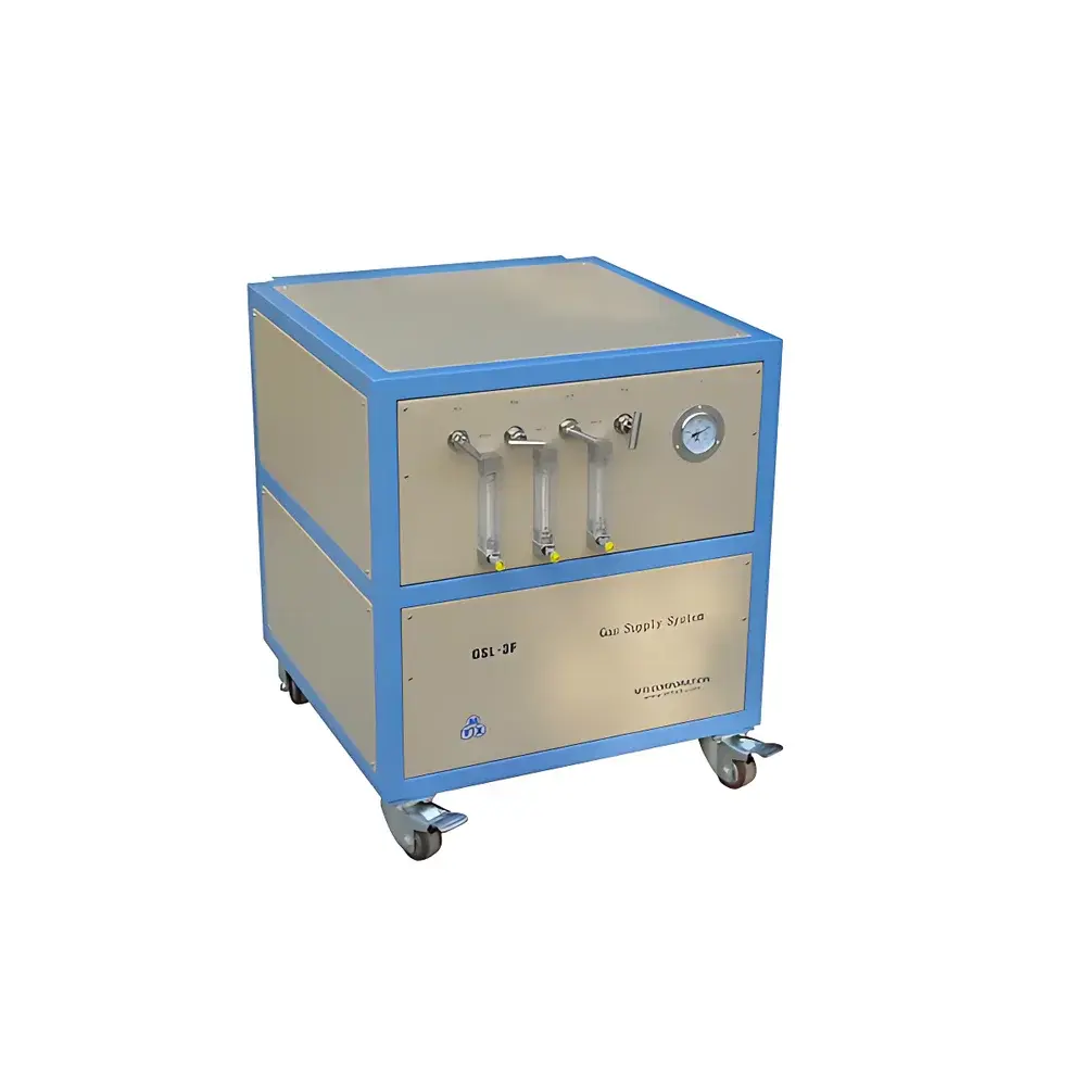
The KJ GROUP GSL-3F Multi-Channel Float-Type Gas Flow Control System is an engineered solution for precise, stable, and contamination-free delivery of up to three process gases in low-pressure, low-flow thermal processing environments. Designed explicitly for integration with horizontal tube furnaces, CVD reactors, and annealing systems, the GSL-3F operates on the principle of variable-area (rotameter) flow measurement—where gas flow lifts a calibrated float within a tapered glass or metal tube, providing real-time, linearly scaled visual indication of volumetric flow rate under defined pressure and temperature conditions. Its architecture prioritizes inert gas integrity: by enabling sequential or simultaneous multi-gas introduction without atmospheric intrusion, it supports reproducible studies of gas-phase reaction kinetics, surface adsorption behavior, and atmosphere-dependent phase transformations in functional materials research.
Key Features
- Triple independent gas channels with individual float flowmeters, each equipped with a high-integrity 1/4″ stainless steel manual shut-off valve rated for pressures up to 1.0 MPa—ensuring leak-tight isolation during gas switching or maintenance.
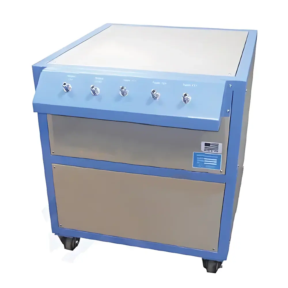
- Front-panel-aligned instrumentation layout: all flow tubes and the dual-scale pressure/vacuum gauge are mounted on a single vertical plane, minimizing parallax error and enabling rapid, operator-initiated verification of system status.
- Modular stainless steel manifold assembly using standardized 1/4″ compression fittings (OD 6.35 mm), facilitating tool-free disassembly, component replacement, and cleaning—critical for maintaining purity in high-vacuum or ultra-high-purity (UHP) gas applications.
- Integrated mixing chamber (Ø80 mm × 140 mm) constructed from electropolished 316L stainless steel, designed to homogenize gas streams prior to furnace inlet while minimizing dead volume and residence time-induced back-diffusion.
- Calibrated float flowmeters covering three standard ranges (10–100, 16–160, and 25–250 mL/min), each traceable to NIST-traceable standards under reference conditions (20 °C, 101.325 kPa, dry air), with typical accuracy of ±2% FS for laminar, non-pulsating flows.
Sample Compatibility & Compliance
The GSL-3F is compatible with inert (Ar, N₂, He), reducing (H₂, forming gas), oxidizing (O₂, air), and reactive precursor gases (NH₃, SiH₄, PH₃) when used with appropriate material selections (e.g., VCR fittings for H₂, EP-grade tubing for UHP service). All wetted parts—including flow tubes, valves, mixing chamber, and tubing—are fabricated from 316L stainless steel or borosilicate glass, ensuring resistance to corrosion and outgassing. The system conforms to general laboratory safety requirements per ISO 10523 (gas handling), and its mechanical design aligns with ASME B31.3 process piping guidelines for low-pressure gas distribution. While not intrinsically certified for hazardous area use, it may be installed in Class 1000–10,000 cleanrooms and integrated into GLP-compliant material synthesis workflows where audit-ready documentation of gas composition and flow history is required.
Software & Data Management
The GSL-3F is a manually operated, analog control system with no embedded electronics or digital interface. Flow and pressure data are read directly from calibrated analog gauges, supporting manual logging in accordance with ASTM E29 or ISO/IEC 17025 documentation practices. For laboratories requiring electronic recordkeeping, optional third-party digital pressure transducers (e.g., Validyne DP15) or flow sensors (e.g., Brooks Instrument SLA Series) can be retrofitted at designated tap points, enabling integration with LabVIEW, MATLAB, or SCADA platforms. All analog readings support 21 CFR Part 11-compliant manual entry into ELN systems when paired with defined SOPs for instrument calibration (per ISO/IEC 17025), interval verification (quarterly), and operator training records.
Applications
- Controlled-atmosphere thermal treatment of 2D materials (graphene, TMDs) in quartz tube furnaces.
- Multi-step CVD processes requiring sequential NH₃ annealing followed by H₂ reduction without air exposure.
- Gas-dependent sintering studies of solid-state electrolytes under mixed O₂/N₂ atmospheres.
- In-situ XRD or Raman experiments where precise, repeatable gas stoichiometry must be maintained across multiple heating cycles.
- Calibration and validation of mass flow controllers (MFCs) using the GSL-3F’s traceable rotameter outputs as reference standards.
FAQ
Can the GSL-3F be used with corrosive gases such as Cl₂ or HF?
No—standard GSL-3F configurations are not rated for halogenated or highly corrosive gases. Custom variants with Hastelloy C-276 valves, PFA-lined flow tubes, and specialized sealing materials are available upon engineering review.
Is flow calibration performed at the factory, and is a certificate provided?
Yes—each float flowmeter is individually calibrated using dry air at 20 °C and 101.325 kPa. A factory calibration report (including as-found/as-left data and uncertainty budget) is supplied with every unit.
What is the maximum allowable inlet pressure for the GSL-3F?
The system is rated for continuous operation up to 0.6 MPa (gauge) at the main inlet; individual channel shut-off valves are rated to 1.0 MPa.
Can additional gas channels be added post-purchase?
Yes—the modular manifold design allows field expansion to four or five channels using OEM-compatible extension kits, subject to revised pressure drop analysis and flow range recalibration.
Does the mixing chamber introduce significant backpressure or flow restriction?
At nominal flow rates ≤250 mL/min, the pressure drop across the Ø80 × 140 mm mixing chamber is <0.5 kPa—verified by computational fluid dynamics (CFD) modeling and validated via differential pressure testing per ISO 5167-2.


