Hprobe Speed-Up Wafer-level Magnetic Test System
| Brand | Pri-eco |
|---|---|
| Origin | France |
| Manufacturer | Hprobe SAS (distributed by Pri-eco) |
| Category | Import |
| Model | Speed-Up Wafer-level Magnetic Test |
| Pricing | Upon Request |
Overview
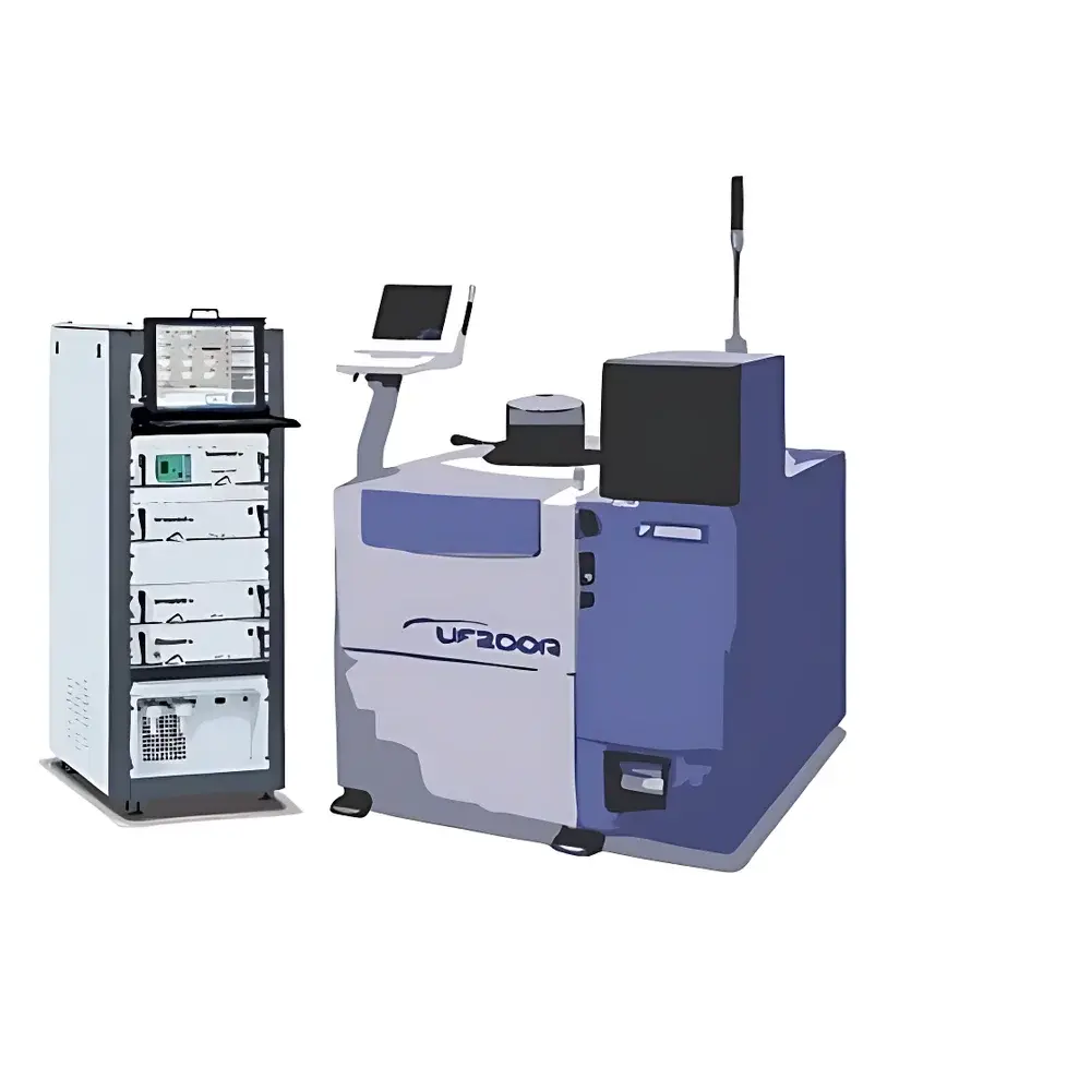
The Hprobe Speed-Up Wafer-level Magnetic Test System is a turnkey, industrial-grade platform engineered for magnetic characterization and electrical testing of magnetic devices directly at the wafer level under precisely controlled 3D magnetic fields. Built upon a patented triaxial magnetic field generator integrated into a semiconductor-grade prober architecture, the system enables full vector control of static, dynamic, and rotating magnetic fields—up to ±2 T—with sub-degree angular accuracy and real-time field calibration. Unlike conventional benchtop magnetometers or discrete electromagnet setups, this system delivers localized, uniform magnetic excitation within a tightly constrained air gap (<1 mm) between the field generator and the wafer surface—ensuring high spatial fidelity and minimal field distortion during probing. It is purpose-built for R&D, process development, and high-volume manufacturing qualification of spintronic and magneto-resistive devices—including STT-MRAM, SOT-MRAM, voltage-controlled MRAM, AMR/GMR/TMR sensors, and magnetic MEMS—under conditions fully compliant with SEMI, ISO/IEC 17025, and GLP-aligned test workflows.
Key Features
- Triaxial magnetic field generation with independent X/Y/Z axis control, enabling arbitrary field orientation and continuous rotation (including elliptical and circular polarization)
- Integrated 3D Hall sensor calibration probe with ±0.1° angular resolution, 5 V/T sensitivity, ±2 T range, differential output, and on-chip temperature compensation (<100 ppm/°C)
- Wafer handling compatibility from 100 mm (manual) to 300 mm (fully automated), including thermal chucks (−60 °C to +150 °C), vision-assisted probe alignment, auto-loaders, and broken-wafer support
- Modular instrumentation suite: dual-channel SMUs (20 mV–200 V / 1 nA–1 A), 18-bit DMMs (10 nV resolution, >1 µs sampling), 40 MHz AWGs (250 MS/s, <1 Mpoint/channel), and ultrafast pulse generators (300 ps min. width, <70 ps 20–80% rise/fall)
- Fully programmable test software supporting three operational modes: Calibration (field mapping & coil current profiling), Engineering (custom script execution, parameter sweeps, (I,V,H) phase-space acquisition), and Production (recipe-based, cycle-optimized test sequences)
- Native support for standard probe cards and RF/micromanipulator configurations; field gap maintained ≤1 mm for optimal field homogeneity and signal integrity
Sample Compatibility & Compliance
The system accommodates magnetic thin-film structures fabricated on Si, SOI, or compound semiconductor wafers (100–300 mm diameter), including patterned MTJ stacks, spin-valve sensors, and magnetic tunnel junction arrays. Its mechanical and electrical design conforms to SEMI E10 (Specification for Definition and Measurement of Equipment Reliability and Maintainability) and SEMI E39 (Standard for Automated Material Handling Interfaces). All instrumentation modules meet IEC 61000-4 electromagnetic compatibility requirements. Software supports audit-trail logging, user access control, and electronic signature functionality aligned with FDA 21 CFR Part 11 for regulated environments. Calibration procedures follow traceable NIST-referenced methodologies, and field uniformity maps are generated per ISO/IEC 17025 Annex A.5 guidelines for measurement uncertainty quantification.
Software & Data Management
Hprobe’s proprietary TestSuite software provides a unified interface for instrument orchestration, field control, data acquisition, and post-processing. It features Python API integration for custom algorithm deployment (e.g., switching probability modeling, write-error-rate analysis), built-in statistical process control (SPC) dashboards, and export to HDF5, CSV, and industry-standard .tdms formats. Raw field calibration data—including spatial B-field vectors, temperature-corrected Hall outputs, and coil current-to-field transfer functions—is stored with metadata (timestamp, operator ID, wafer ID, site coordinates) to enable full metrological traceability. The software supports batch-mode execution across multiple die sites, automatic defect flagging based on user-defined pass/fail thresholds, and real-time visualization of (Hx, Hy, Hz) trajectories during rotating field sweeps.
Applications
- STT-MRAM: Write error rate (WER) vs. field angle, critical switching current density (Jc0) extraction, thermal stability factor (Δ) mapping
- SOT-MRAM: Spin-orbit torque efficiency (ξDL) quantification, field-like torque separation, domain wall nucleation field determination
- TMR/MTJ sensors: Tunnel magnetoresistance ratio (TMR%), linear range optimization, hysteresis loop asymmetry analysis under bias
- Magnetic MEMS: Resonant frequency shift under field, Lorentz-force actuation linearity, damping coefficient extraction
- Material screening: Perpendicular magnetic anisotropy (PMA) strength assessment, exchange bias training behavior, interlayer coupling evaluation
- Process monitoring: Lot-to-lot magnetic uniformity tracking, mask alignment impact on field response, annealing-induced anisotropy evolution
FAQ
What wafer sizes does the Speed-Up system support?
The platform supports 100 mm, 150 mm, 200 mm, and 300 mm wafers, with configuration options ranging from manual load-and-probe stations to fully automated production probers with integrated thermal chucks and vision systems.
Is the magnetic field generator compatible with RF probing?
Yes—provided the RF probes maintain ≥1 mm clearance from the field generator faceplate to avoid eddy-current heating and field perturbation. Custom low-interference RF probe holders and magnetic shielding kits are available upon request.
How is field calibration performed in situ?
Calibration uses the embedded 3D Hall sensor array mounted on the chuck. Users execute a multi-point field sweep across the target die area; the system records local Bx, By, Bz values and generates a per-site correction matrix applied in real time during subsequent measurements.
Can the system perform pulsed-field testing synchronized with electrical stimuli?
Yes—the pulse generator triggers are fully synchronized with SMU sourcing, AWG waveform playback, and data acquisition clocks (jitter <35 ps RMS), enabling sub-nanosecond timing alignment for write-pulse reliability studies.
Does the software support automated yield analysis across full wafers?
Yes—TestSuite includes wafer-map overlay functionality with color-coded pass/fail metrics, binning logic based on multi-parameter criteria (e.g., RAP/RP, WER, switching field distribution), and export to industry-standard GDSII-compatible yield formats.


