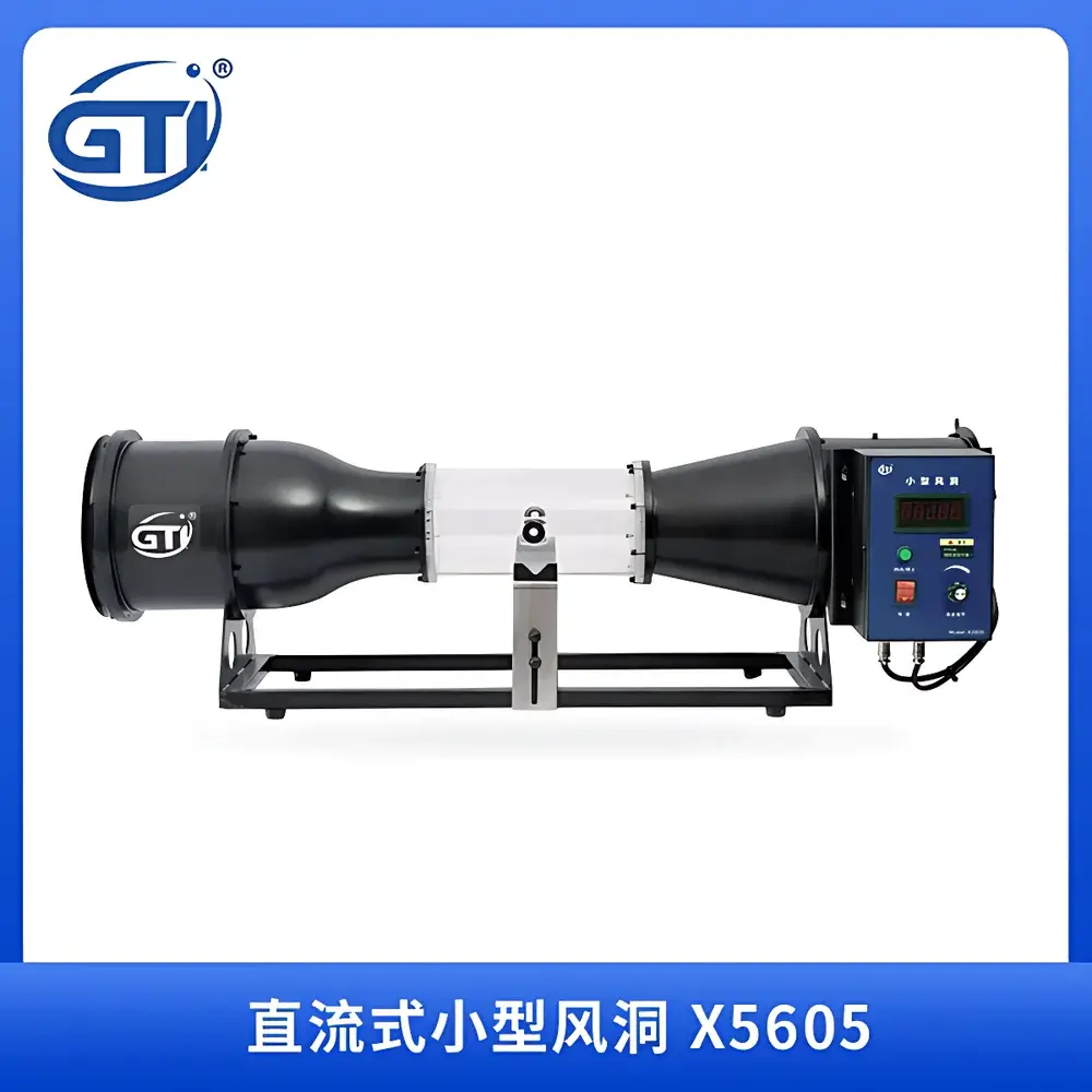
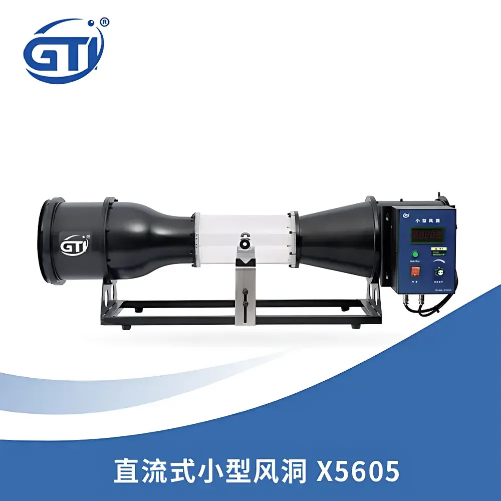
GTI X5605 DC-Type Compact Wind Tunnel
| Brand | GTI |
|---|---|
| Origin | Liaoning, China |
| Manufacturer Type | Authorized Distributor |
| Country of Origin | China |
| Model | X5605 |
| Power Supply | AC 220 V, 50 Hz, 450 W |
| Weight | ~20 kg |
| Test Section Dimensions | 230 mm (L) × φ120 mm (ID) |
| Test Port Diameter | φ2–20 mm |
| Wind Speed Range | 1–30 m/s |
| Tunnel Type | DC suction-type |
| Flow Uniformity | Enhanced by internal honeycomb flow straightener |
| External Dimensions | 1002 × 237 × 319 mm |
Overview
The GTI X5605 DC-Type Compact Wind Tunnel is an engineered laboratory-scale aerodynamic test system designed for precision airflow calibration, sensor validation, and small-scale model testing. Operating on a suction-driven direct-current (DC) airflow principle, the tunnel generates a controlled, laminar-dominated flow field within its cylindrical test section. Its core function is to provide traceable, repeatable wind speeds from 1 to 30 m/s—enabling quantitative characterization of anemometers, Pitot tubes, thermal probes, and miniature aerodynamic models under standardized conditions. Unlike open-loop or fan-bench setups, the X5605 integrates a calibrated axial blower with variable-speed control and a built-in honeycomb flow straightener to minimize turbulence intensity (<2.5% at mid-range velocities) and ensure axial flow alignment within ±1.2° tolerance relative to the tunnel centerline. This architecture supports metrological-grade verification in accordance with ISO/IEC 17025-accredited calibration workflows and aligns with foundational practices outlined in ASTM D5096 (Standard Practice for Calibration of Anemometers) and ISO 6446 (Wind tunnel calibration of air velocity sensors).
Key Features
- Stable, adjustable wind speed output from 1 to 30 m/s with <±0.3 m/s repeatability across three consecutive cycles at fixed setpoints
- Integrated honeycomb flow conditioner upstream of the test section to suppress swirl and lateral velocity gradients, ensuring uniform axial velocity distribution (CV ≤ 4.8% across φ120 mm cross-section)
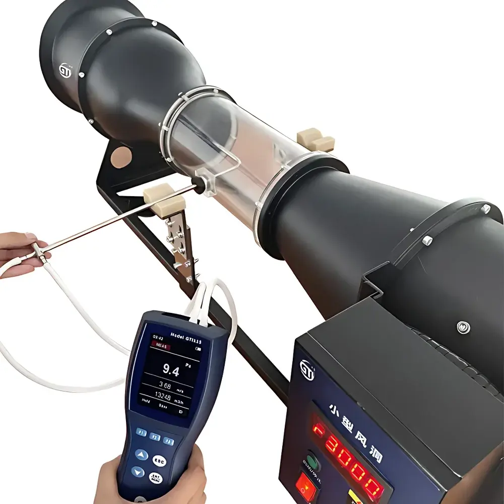
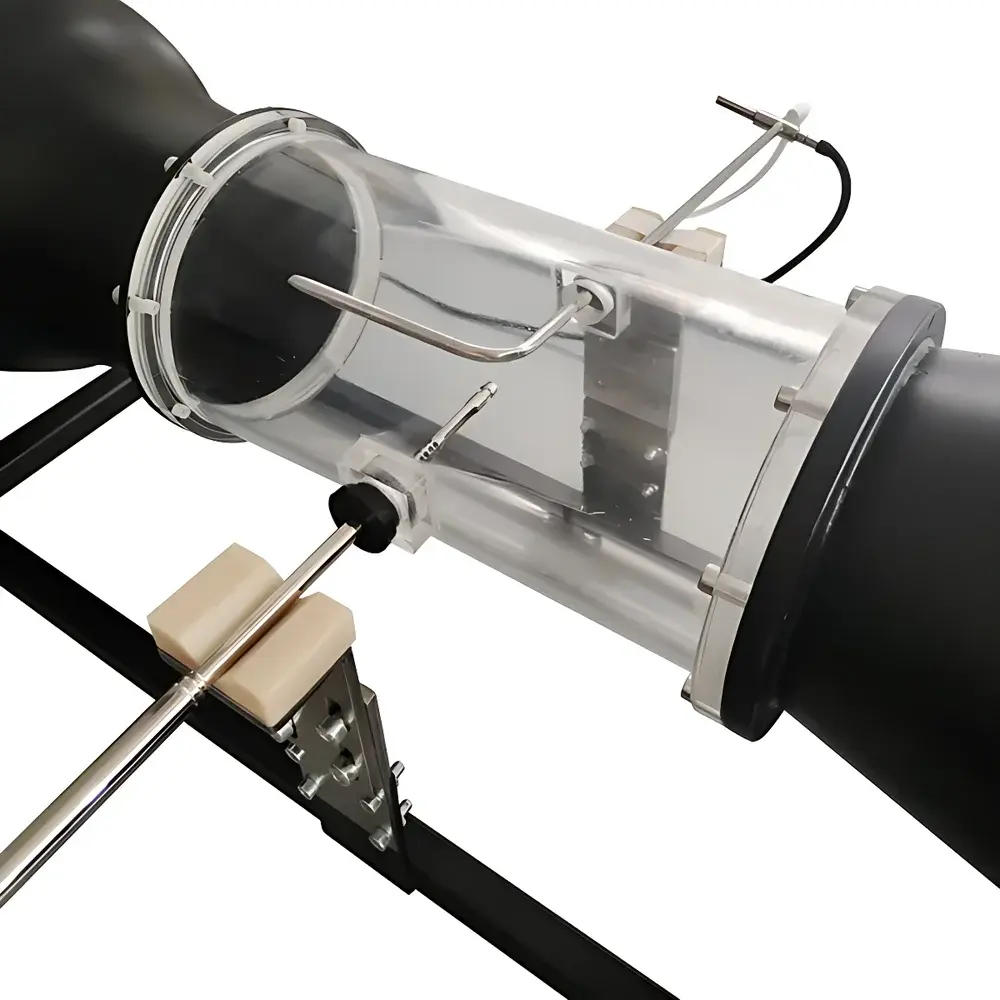
- Optically transparent acrylic test section (230 mm long × φ120 mm inner diameter) enabling real-time flow visualization via smoke wire, laser sheet, or particle imaging techniques
- Modular test port configuration with interchangeable collars accommodating sensor diameters from φ2 mm to φ20 mm—compatible with standard NPT and metric threaded mounts
- Compact footprint (1002 × 237 × 319 mm) and self-supporting mechanical design requiring no external anchoring, vibration isolation pads, or auxiliary support frames
- Front-panel digital speed controller with analog voltage input option (0–10 V DC) for integration into automated test benches or PLC-controlled environments
Sample Compatibility & Compliance
The X5605 accommodates a broad range of physical test objects: handheld cup-vane and hot-wire anemometers, differential pressure-based Pitot-static tubes, MEMS flow sensors, 1:20–1:50 scale aerodynamic models (e.g., UAV wings, HVAC grilles), and surface-mounted static pressure taps. Its test section geometry permits six-component force/moment measurements when paired with compatible balance systems (e.g., ATI Nano17 or Futek LSB200). The tunnel meets essential mechanical and electrical safety requirements per GB 4793.1–2019 (equivalent to IEC 61010-1) and supports GLP-compliant documentation through optional timestamped data logging. While not certified to ISO 17025 itself, it serves as a primary reference system for in-house calibration labs seeking accreditation under CNAS or A2LA frameworks.
Software & Data Management
The X5605 operates as a hardware-calibrated instrument without proprietary firmware dependencies. Speed setpoints are controlled via analog input or manual potentiometer; real-time velocity monitoring requires external instrumentation (e.g., NIST-traceable reference anemometer + DAQ system). For audit-ready workflows, users may integrate the tunnel into LabVIEW, MATLAB, or Python-based acquisition platforms using standard USB-TTL or Ethernet-enabled DAQ modules. All calibration records—including date, operator ID, reference standard ID, environmental conditions (T, P, RH), and deviation reports—must be maintained externally per FDA 21 CFR Part 11 principles if used in regulated quality assurance settings.
Applications
- Primary calibration of Class II and III anemometers per ISO 9001 Clause 7.1.5.2 and ISO/IEC 17025 Clause 6.4.10
- Validation of computational fluid dynamics (CFD) boundary conditions using experimental velocity profiles
- Educational demonstrations of boundary layer development, separation, and wake formation using smoke visualization
- Functional testing of HVAC airflow sensors prior to field deployment
- Pre-certification screening of drone propeller aerodynamics and drag coefficient estimation
- Smoke trail analysis for ventilation efficiency studies in cleanroom or pharmaceutical facility design
FAQ
Is the X5605 suitable for ISO/IEC 17025 accredited calibrations?
Yes—as a reference wind source, provided the user maintains documented traceability to national standards (e.g., via NIM or NIST-traceable transfer standards) and implements full uncertainty budgeting per GUM (JCGM 100:2008).
Can the test section accommodate a 1:10 scale automobile model?
No—the maximum model envelope is constrained by the φ120 mm internal diameter; recommended scale limits are ≤1:30 for full-body configurations.
Does the system include a built-in velocity measurement sensor?
No—velocity verification must be performed externally using a calibrated reference probe mounted at the test section centerline.
What maintenance intervals are recommended for long-term stability?
Blower motor bearings should be inspected annually; honeycomb elements require cleaning every 200 operational hours using compressed dry air or ultrasonic isopropyl alcohol bath.
Is remote operation supported via Ethernet or RS-485?
Not natively—but analog speed control (0–10 V DC) enables seamless integration with industrial controllers supporting Modbus RTU or EtherCAT protocols via third-party signal converters.
Related Products