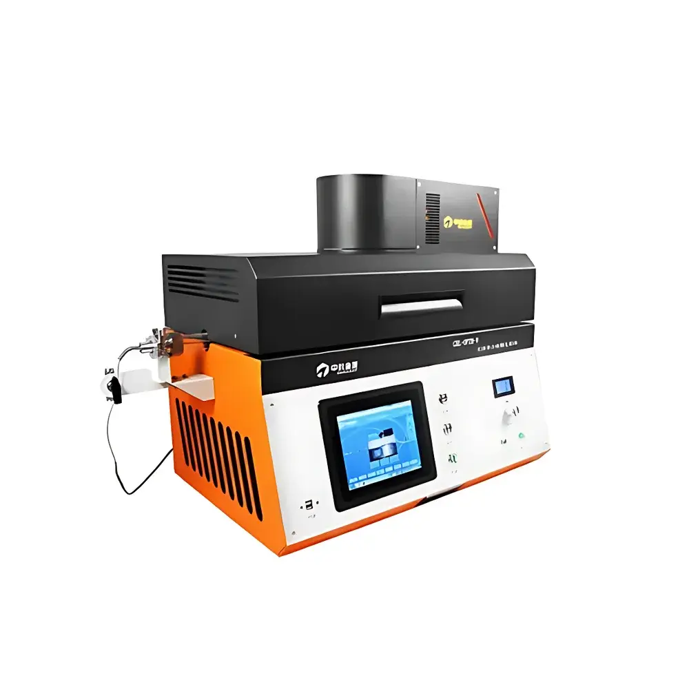
CEL-OPTH-V Photoinduced Synthesis and Photothermal Catalysis System (with Integrated Xenon Light Source)
| Brand | CEL (China Education Goldsource) |
|---|---|
| Origin | Beijing, China |
| Manufacturer Type | OEM Manufacturer |
| Product Origin | Domestic (China) |
| Model | CEL-OPTH-V |
| Pricing | Upon Request |
Overview
The CEL-OPTH-V Photoinduced Synthesis and Photothermal Catalysis System is an integrated laboratory platform engineered for precise, simultaneous control of high-temperature thermal processing and broadband optical irradiation—enabling true photothermal catalytic synthesis and activity evaluation under controlled atmospheres. At its core, the system implements a coaxial photothermal reaction architecture: a three-zone programmable high-temperature furnace (up to 800 °C) houses a UV-grade fused silica reaction tube (30 mm OD), while a collimated 300 W xenon lamp—equipped with M62-threaded filter mounts—is optically coupled via a quartz light guide to deliver uniform irradiance (500–2000 mW/cm²) directly onto the catalyst sample positioned within the heated isothermal zone (±1 °C uniformity over 30 mm). This design ensures that photons penetrate radially into the reaction bed *during* active thermal treatment, eliminating sequential or decoupled light/heat protocols and enabling mechanistic studies of synergistic photoexcitation and thermally activated surface reactions in solid-state catalysis.
Key Features
- Triple-zone resistive heating (1 kW per zone, 3 kW total) with independent PID control, achieving 0.1 °C setpoint resolution and ±1 °C axial temperature uniformity across a 30 mm working zone
- Optically transparent high-purity quartz reactor tube (30 mm diameter) with integrated quartz sample holder, compatible with UV–Vis–NIR irradiation (200–2500 nm)
- Integrated 300 W xenon arc lamp with adjustable focusing head, modular filter compatibility (M62 thread), and real-time power density calibration (500–2000 mW/cm² at sample plane)
- Full gas-handling capability: vacuum evacuation (down to 10⁻³ Pa with optional molecular pump station), inert atmosphere purging, and precision gas dosing via mass flow controllers (MFCs) or rotameters
- Modular expandability: standardized mechanical and electrical interfaces allow seamless integration of high-vacuum systems, multi-gas blending modules, and analytical instrumentation (e.g., GC, IC, chemiluminescence NOx analyzers)
- Industrial-grade control interface: 8-inch HMI touchscreen running Kingview SCADA software with configurable alarm logic (over-temperature cutoff, thermal runaway detection, interlock monitoring)
Sample Compatibility & Compliance
The CEL-OPTH-V accommodates powdered, pelletized, or thin-film catalyst samples (≤10 mm diameter) placed on the quartz stage inside the reaction tube. Its all-quartz optical path and high-temperature stability support experiments under oxidizing, reducing, or inert atmospheres—including H₂, O₂, CO₂, N₂, NH₃, and VOC mixtures—while maintaining trace-level contamination control. The system conforms to fundamental engineering safety standards for Class I, Division 2 electrical environments and supports GLP-compliant operation through audit-trail-enabled software logging (timestamped temperature profiles, lamp power history, gas flow records). Optional configurations meet ISO 17025-relevant requirements for catalytic activity benchmarking when paired with certified reference gases and calibrated GC detectors.
Software & Data Management
Control and data acquisition are managed via Kingview-based configuration software with OPC UA server support, enabling third-party integration (LabVIEW, MATLAB, Python via TCP/IP). All operational parameters—including furnace segment temperatures, lamp current/voltage, MFC setpoints, and vacuum pressure—are logged at user-defined intervals (100 ms–10 s) into timestamped CSV files. The system supports 21 CFR Part 11-compliant user authentication, electronic signatures, and immutable audit trails when deployed with optional database archiving. Real-time trend visualization includes dual-axis plots (e.g., conversion vs. time + temperature), with export-ready metadata embedding per ASTM E2915-22 guidelines for catalytic performance reporting.
Applications
- Synthesis and annealing of photocatalytic semiconductors (e.g., g-C₃N₄, TiO₂ polymorphs, BiVO₄, perovskite oxides) under simultaneous UV–Vis irradiation and thermal treatment
- Photothermal CO₂ hydrogenation to CH₄/CO/C₂H₄ using plasmonic Ni–TiO₂ or Cu–CeO₂ catalysts
- Gas-phase photocatalytic oxidation of formaldehyde, toluene, NOx, and SOx under simulated ambient or industrial flue gas conditions
- Photo-assisted ammonia synthesis via lithium-mediated nitrogen fixation at sub-ambient pressures
- Quantitative evaluation of apparent quantum yield (AQY) and turnover frequency (TOF) under isothermal photothermal steady-state conditions
- In situ/operando studies coupling with FTIR, Raman, or XRD when interfaced with external beamlines or fiber-optic probes
FAQ
What spectral range does the built-in xenon lamp cover, and how is spectral selectivity achieved?
The 300 W xenon lamp emits broadband radiation from 200 nm (deep UV) to 2500 nm (short-wave IR). Spectral filtering is accomplished via interchangeable M62-threaded optical filters (e.g., UG11 for UV cut-on, BG40 for visible bandpass, RG9 for NIR transmission), mounted directly in the lamp housing’s rotating turret.
Can the system operate under vacuum while maintaining optical access and thermal stability?
Yes—the quartz reactor tube is sealed with vacuum-rated CF-35 flanges and compatible with optional 10⁻³ Pa molecular pumping stations. The light guide maintains alignment under vacuum due to rigid kinematic mounting, and temperature uniformity remains unaffected by pressure changes below 100 Pa.
Is the furnace cooling rate controllable, and what is the typical quench time from 800 °C to 100 °C?
Active air-cooling via integrated centrifugal blowers enables programmable ramp-down rates (0.1–20 °C/min). From 800 °C to 100 °C, the default forced-air cooldown requires ~18 minutes; faster quenching (≤5 min) is achievable with optional water-jacketed outer shielding.
How is gas flow distribution optimized to ensure uniform contact with the irradiated catalyst bed?
Gas enters axially through a 3 mm stainless-steel capillary terminating just above the sample stage, creating laminar downflow across the entire catalyst cross-section—verified by computational fluid dynamics (CFD) modeling and tracer gas residence time distribution (RTD) measurements.
Are third-party analytical instruments (e.g., Agilent GC, Metrohm IC) supported for online product analysis?
Yes—standard 1/8″ Swagelok ports and 1/4″ VCR fittings enable direct coupling to GC, IC, or MS systems. The control software provides TTL-trigger outputs synchronized with data acquisition start/stop signals, ensuring temporal correlation between reaction conditions and chromatographic peaks.


