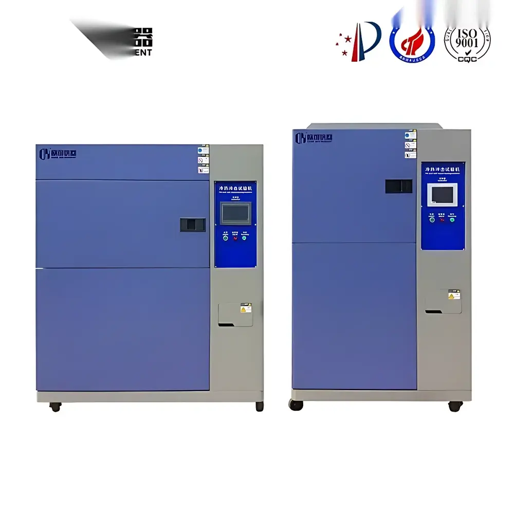
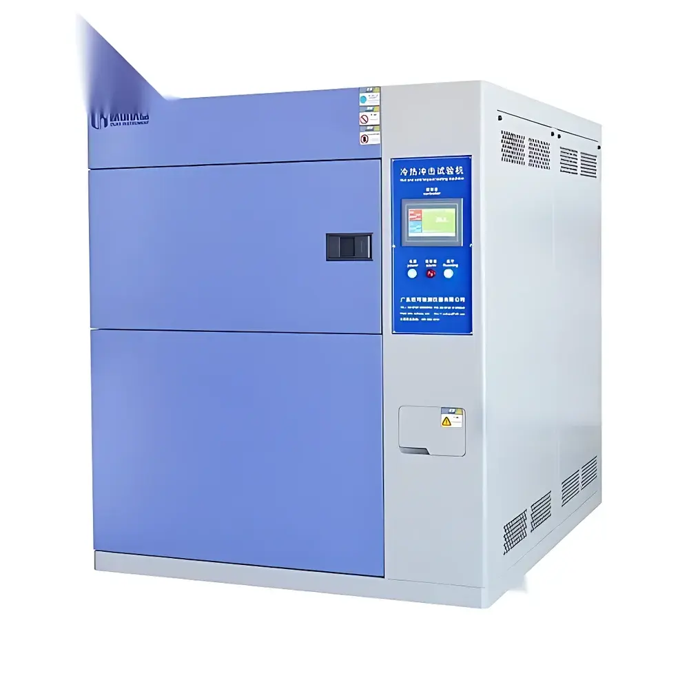
Three-Chamber Thermal Shock Test Chamber
| Key | High-Temp Zone: +60 °C to +200 °C |
|---|---|
| Low-Temp Zone Options | −10 °C to −40 °C / −10 °C to −60 °C / −10 °C to −70 °C |
| Test Chamber Range | 0 °C to −40 °C / −10 °C to −55 °C / −10 °C to −65 °C |
| Temp. Fluctuation | ±0.5 °C |
| Temp. Uniformity | ±3 °C |
| Temp. Recovery Time | 3–5 min |
| Heat-up Rate (HT Zone) | ~5 °C/min (avg.) |
| Cool-down Rate (LT Zone) | ~1.5 °C/min (avg.) |
| Dwell Time per Stage | ≥30 min |
| Transfer Time (Chamber-to-Chamber) | ≤15 s |
Overview
The Three-Chamber Thermal Shock Test Chamber is an engineered environmental stress screening (ESS) system designed for rapid, high-fidelity thermal cycling of electronic components, aerospace assemblies, automotive ECUs, and advanced packaging materials. Unlike two-chamber configurations that rely on mechanical shuttle movement—introducing vibration, positional uncertainty, and thermal lag—this three-zone architecture physically isolates the high-temperature reservoir, low-temperature reservoir, and test chamber. Thermal shock is induced by precisely controlled pneumatic air-valve switching between pre-conditioned hot and cold airstreams, delivering temperature transitions directly into the stationary test zone. This design eliminates specimen motion, ensures repeatable thermal gradients across complex geometries, and conforms to the fundamental principles of accelerated life testing defined in IEC 60068-2-14 and MIL-STD-810H Method 503.4.
Key Features
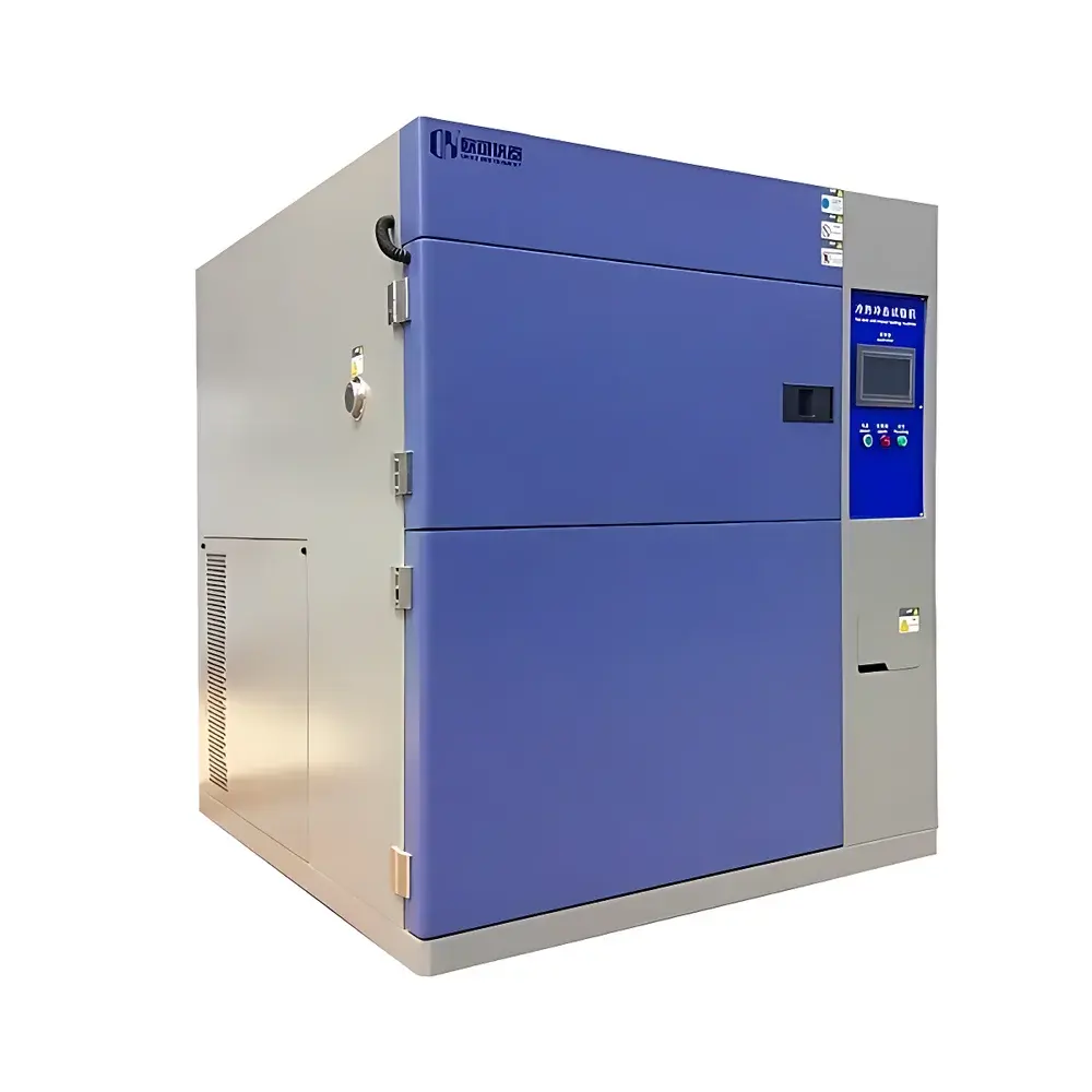
- Triple-zone architecture: independent high-temperature chamber (+60 °C to +200 °C), low-temperature chamber (−10 °C to −70 °C selectable), and static test chamber (operating range down to −65 °C)
- Sub-15-second thermal transfer via optimized air ducting and high-flow pneumatic valves—no mechanical shuttling or specimen displacement
- PID-controlled temperature regulation with ±0.5 °C fluctuation and ±3 °C uniformity across the test volume, verified per ASTM E742
- Programmable dwell time ≥30 minutes per thermal plateau, enabling compliance with JEDEC JESD22-A104 and A106 qualification profiles
- Large-format color LCD touchscreen controller with multilingual (English/Chinese) GUI, 96 built-in test templates, and full curve visualization of setpoint vs. actual response
- PLC-integrated safety architecture: real-time monitoring of compressor discharge pressure, refrigerant saturation, heater current, door interlock, and over-temperature cutoff
- Standard 50 mm diameter access port (left-side) fitted with silicone gasket and brass compression fitting for external power/data feedthrough under operational vacuum or inert gas purge
Sample Compatibility & Compliance
This chamber accommodates specimens up to 500 mm × 500 mm × 500 mm (W×D×H) with unrestricted mounting options—including PCB racks, component trays, and fixture-mounted modules. It supports both non-powered and powered-in-situ testing when integrated with external DC/AC power supplies and signal analyzers via the dedicated test port. The system meets ISO/IEC 17025 calibration traceability requirements when paired with NIST-traceable reference sensors. Its control firmware implements audit-ready event logging (timestamped start/stop, parameter changes, alarms) aligned with GLP and GMP documentation expectations. While not certified to UL 61010-1 out-of-the-box, it complies with EN 61000-6-2 (immunity) and EN 61000-6-4 (emissions) for laboratory installation environments.
Software & Data Management
The embedded controller records all critical parameters—including chamber air temperature (RTD), setpoint deviation, valve actuation status, compressor run time, and heater duty cycle—at user-configurable intervals (1–60 seconds). Raw data exports as CSV files compatible with MATLAB, Python pandas, and JMP for statistical process control (SPC) analysis. Optional Ethernet/IP interface enables remote monitoring via Modbus TCP or OPC UA, supporting integration into centralized MES or SCADA platforms. All configuration changes are logged with operator ID (if network-authenticated), timestamp, and previous/updated values—meeting baseline FDA 21 CFR Part 11 requirements for electronic records when deployed with organizational IT governance policies.
Applications
- Qualification of solder joint reliability in lead-free PCBAs per IPC-9701A
- Validation of MEMS sensor hermeticity and die-attach integrity under extreme ΔT cycling
- Screening of conformal coating adhesion failure modes in automotive lighting modules
- Accelerated aging of lithium-ion battery cell housings and thermal interface materials
- Verification of optical alignment stability in laser diode subassemblies after 500+ shock cycles
- Failure mode analysis (FMA) of ceramic capacitors exhibiting capacitance drift above 1000 cycles
FAQ
What distinguishes a three-chamber thermal shock system from a two-chamber shuttle-type unit?
The three-chamber design eliminates mechanical specimen movement, ensuring zero vibration-induced artifacts and superior thermal repeatability—critical for high-value microelectronics and optomechanical assemblies.
Can this chamber perform standard high-low temperature storage tests without shock cycling?
Yes. It operates independently as a high-temperature oven, low-temperature freezer, or combined environmental chamber using programmable dwell-only profiles.
Is nitrogen purging supported for moisture-sensitive test articles?
The chamber includes a standard inert gas inlet port; optional mass flow controller and O₂ analyzer enable controlled dry-nitrogen purge during low-temperature phases.
How is temperature uniformity validated across the test volume?
Per IEC 60068-3-5, nine-point mapping (3×3 grid at mid-height) is performed using calibrated Class A PT100 probes prior to delivery and annually thereafter.
Does the controller support custom ramp-and-soak profiles beyond preset standards?
Yes—up to 99 segments per program, with independent ramp rate, dwell time, and setpoint definition for each segment, including conditional branching based on elapsed time or thermal deviation thresholds.
Related Products


