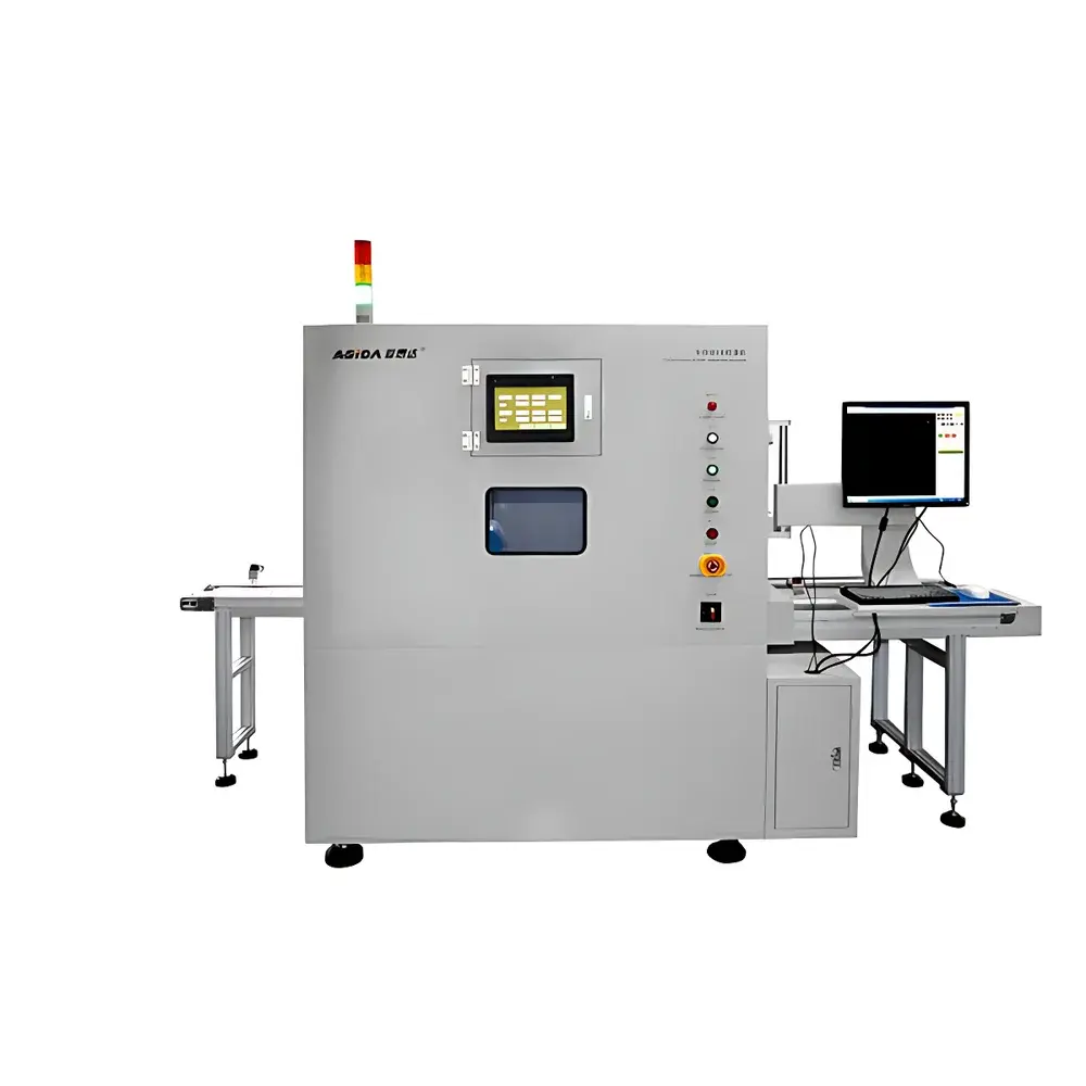
Asida XG5200 Automated X-ray Misalignment Inspection System for Lithium-ion Battery Electrode Tabs
| Key Features | Fully automated inline inspection |
|---|---|
| X-ray tube | 110–130 kV, 300–500 µA, focal spot ≤5 µm |
| Imaging system | 4″/6″ FOV, resolution 75/110 lp/cm, X-CCD 1024×1024 pixels |
| Repeatability | ±40 µm |
| Throughput | ≥12 ppm (4-corner inspection) |
| Cooling | Forced-air |
Overview
The Asida XG5200 Automated X-ray Misalignment Inspection System is an industrial-grade inline non-destructive testing (NDT) platform engineered specifically for lithium-ion battery manufacturing. It employs high-resolution transmission X-ray imaging to quantitatively assess electrode tab alignment and vertical height differentials between anode and cathode layers in wound and pouch-type cells. Unlike conventional visual or contact-based gauging methods, the XG5200 leverages differential X-ray attenuation physics to reconstruct internal structural geometry without physical intervention—enabling sub-50 µm spatial resolution at production-line speeds. The system is deployed downstream of winding or stacking stations to verify geometric integrity prior to thermal pressing, electrolyte filling, or formation cycling. Its design conforms to the functional safety requirements of ISO 13849-1 (PL e) and electromagnetic compatibility standards per IEC 61000-6-2/6-4, ensuring stable integration into Class 1000 cleanroom environments typical of battery cell fabrication lines.
Key Features
- Fully automated workflow: Integrated robotic loading, real-time X-ray acquisition, AI-assisted misalignment quantification, binary OK/NG classification, and pneumatic sorting—all executed without operator intervention.
- Multi-model configurability: Supports up to 60 distinct battery geometries via user-defined measurement templates; automatic model recall triggered by 1D/2D barcode or QR code scanning on cell housings.
- Intelligent dual-model pairing: Proprietary software algorithm identifies A- and B-type cells based on tab offset signatures and performs deterministic AB pairing prior to conveyor transfer—critical for balanced module assembly.
- Unified diagnostic interface: Simultaneous display of multi-angle X-ray projections (top, side, corner), dimensional overlays, deviation heatmaps, and pass/fail metrics within a single GUI window—optimized for rapid root-cause analysis.
- Comprehensive system telemetry: Continuous logging of motor encoder positions, X-ray tube voltage/current stability, detector gain calibration status, conveyor speed synchronization, and interlock circuit integrity—accessible via embedded web server.
- Radiation-hardened safety architecture: Triple-redundant shielding (lead-lined enclosure, beam collimation shutter, door-mounted microswitch interlocks), validated to deliver ≤1 µSv/hr at 5 cm from any external surface—meeting EU Directive 2013/59/Euratom and FDA 21 CFR Part 1020.40 requirements.
Sample Compatibility & Compliance
The XG5200 accommodates soft-pack pouch cells (L × W × H: 100–350 mm × 50–200 mm × 3–15 mm) and cylindrical/wound prismatic formats (diameter ≤80 mm, height ≤250 mm). It supports both dry-cell and pre-filled configurations, with no restriction on electrolyte composition or separator material (polyolefin, ceramic-coated, or solid-state). All measurement algorithms are traceable to NIST-traceable step gauges and certified reference artifacts. The system’s inspection logic complies with UL 1642 Annex E (cell mechanical integrity verification) and supports audit-ready reporting aligned with ISO 9001:2015 clause 8.5.1 and IATF 16949 section 8.5.1.2. Radiation emission certification documentation—including type test reports from CNAS-accredited laboratories—is supplied with each unit.
Software & Data Management
Control and analysis are managed through Asida VisionSuite™ v4.2—a Windows-based application built on .NET Framework 4.8 with SQL Server Express backend. The software enforces role-based access control (RBAC), full audit trail logging (per FDA 21 CFR Part 11 Annex 11), and encrypted database backups. Measurement data (X-ray images, coordinate deviations, classification flags, timestamped metadata) is exported in standardized formats: DICOM SR for medical-grade archiving, CSV for SPC charting in Minitab/JMP, and JSON for MES/SCADA integration via RESTful API. Calibration records, maintenance logs, and user activity history are retained for ≥36 months and support GLP/GMP-compliant electronic signature workflows.
Applications
- Quantitative assessment of anode/cathode tab vertical offset in wound LiCoO₂/NMC/graphite cells.
- Detection of foil wrinkling, delamination-induced air gaps, and current collector misalignment during high-speed winding.
- Verification of tab weld positioning consistency across multiple production shifts.
- Statistical process control (SPC) of electrode stack height variance in automotive-grade 21700 and 4680 cells.
- Root-cause correlation between tab misalignment and post-formation capacity loss or impedance rise.
- Support for APQP Stage 3 (Production Part Approval Process) submissions requiring 100% incoming inspection evidence.
FAQ
What X-ray energy range is used, and how is beam hardening compensated?
The system operates at 110–130 kV with programmable current (300–500 µA); beam hardening is mitigated via dual-energy subtraction using pre-calibrated aluminum filtration and real-time detector gain normalization.
Can the XG5200 integrate with existing factory MES or SCADA systems?
Yes—via OPC UA (IEC 62541) and Modbus TCP protocols; all inspection results, cycle times, and alarm events are mapped to standard ISA-88/ISA-95 data tags.
Is offline calibration required, and how often?
No routine offline calibration is needed; daily automated self-checks validate geometric distortion correction using embedded fiducial markers; full recalibration is recommended every 12 months or after mechanical impact.
Does the system support custom defect classification beyond tab misalignment?
Yes—users may define additional detection rules (e.g., foreign object debris, foil tears, weld voids) using the integrated image processing script editor with OpenCV 4.5 libraries.
What is the mean time between failures (MTBF) under continuous 24/7 operation?
Based on field data from 47 deployed units, MTBF exceeds 12,500 hours; critical subsystems (X-ray tube, detector, motion controller) are hot-swappable with <15-minute downtime.
Related Products


