YANRUN HMAS-HT Full-Temperature-Field Ultra-High-Temperature Vickers Hardness Indentation System
| Brand | YANRUN |
|---|---|
| Origin | Shanghai, China |
| Manufacturer Type | Direct Manufacturer |
| Instrument Type | Vickers Hardness Tester |
| Operating Temperature Range | 400–1600 °C |
| Maximum Furnace Temperature | 1750 °C |
| Load Capacity | 0.4–60 kgf (3.92–588 N) |
| Force Resolution | 0.01 % FS |
| Force Accuracy | ±0.3 % FS |
| Positioning Accuracy | ≤±1 µm |
| Positioning Resolution | 0.01 µm |
| X/Y/Z Travel | 300 × 150 × 50 mm |
| Optical Magnification (at 1600 °C) | 880× / 1760× |
| Objective Lenses | 10× / 20× (rated to 1600 °C) |
| Field of View (1600 °C) | 800 µm / 400 µm |
| Optical Resolution | 4.2–1.1 µm |
| Atmosphere | High-purity argon (≤1 ppm O₂/H₂O) |
| Cooling | Dual-mode (forced-air + inert-gas convection) |
| Sample Size Limit | Ø60 mm × 60 mm |
| In-situ Dwell Time at 1600 °C | ≥3 h |
| Indenter Material | Sintered refractory ceramic (1700 °C repairable, flexural strength ≥430 MPa, fracture toughness ≥5.8 MPa·m½) |
Overview
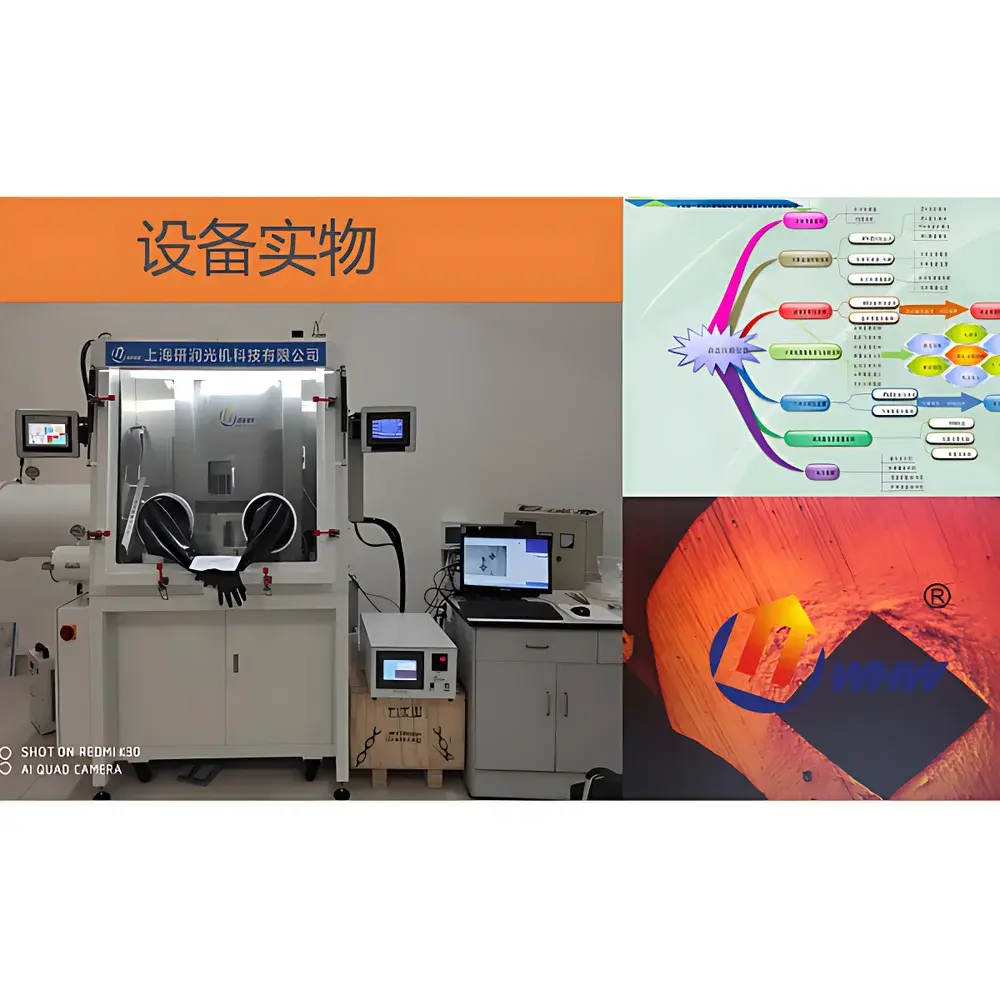
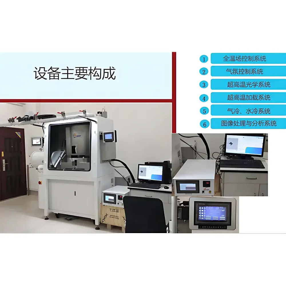
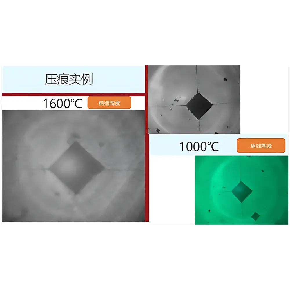
The YANRUN HMAS-HT is an ultra-high-temperature in-situ indentation system engineered for quantitative mechanical characterization of advanced materials under extreme thermal conditions. Unlike conventional hardness testers limited to ambient or moderate temperatures, the HMAS-HT implements a full-temperature-field design—enabling continuous Vickers indentation, load-displacement-time curve acquisition, and real-time optical imaging *within a stabilized 1600 °C isothermal environment*. Its core measurement principle integrates high-precision electro-mechanical force actuation with high-stability optical metrology inside a vacuum-compatible, argon-purged furnace chamber. The system operates on the standardized Vickers hardness test methodology (ASTM E384, ISO 6507), extended rigorously to elevated temperatures via traceable force calibration, thermally compensated displacement sensing, and refractory-grade indenter geometry retention. It supports not only hardness mapping but also derived mechanical parameters—including elastic modulus (via unloading slope analysis), fracture toughness (via Palmqvist or median crack models), residual stress (through indentation-induced strain field analysis), and microstructural evolution (via in-situ metallography). Designed for research-grade reproducibility, it meets structural requirements for GLP-compliant high-temperature material qualification.
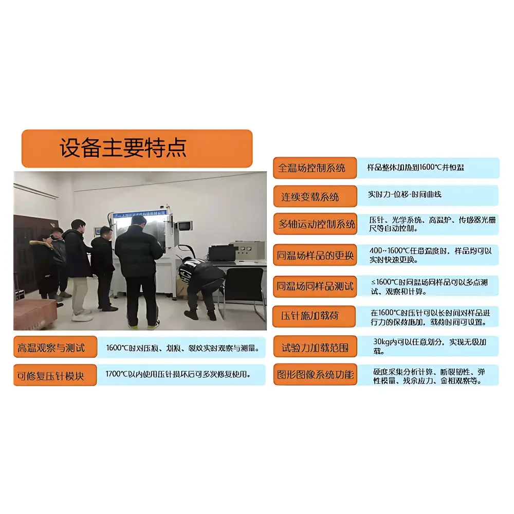
Key Features
- True in-situ operation at up to 1600 °C: All functional modules—including load application, dwell, optical imaging, and data acquisition—remain fully operational within the nominal working temperature range.
- Full-temperature-field architecture: Uniform thermal distribution across the entire sample stage and indenter path eliminates thermal gradient artifacts during loading and imaging.
- Refractory indenter system: 110 mm sintered ceramic indenter rated to 1700 °C; capable of ≥100 h cumulative service life with on-site refurbishment; mechanical properties certified (flexural strength ≥430 MPa; fracture toughness ≥5.8 MPa·m½).
- Nanometer-class motion control: Five-axis servo-driven positioning with ≤±1 µm accuracy and 0.01 µm resolution; programmable velocity from 1 to 50,000 µm/s.
- High-fidelity optical subsystem: Dual-objective (10×/20×) lens assembly with ≥40 mm clear aperture; optimized for thermal stability at 1600 °C; optical resolution 1.1–4.2 µm; real-time image capture at 880×/1760× magnification on 21.5″ display.
- Dual cooling architecture: Segregated forced-air (≤0.1 CFM × 4) and inert-gas convection modules maintain external electronics and optical train below 50 °C while sustaining internal furnace integrity.
- Modular atmosphere management: Continuous high-purity argon purge (<1 ppm O₂/H₂O); 4-phase inert gas flow control; automated chamber evacuation and refill sequence.
Sample Compatibility & Compliance
The HMAS-HT accommodates bulk specimens up to Ø60 mm × 60 mm, including monolithic ceramics (e.g., ZrO₂, SiC, Al₂O₃), refractory metals (Mo, W, Nb alloys), CMCs, and thermal barrier coatings. Its design conforms to key regulatory and standards frameworks applicable to high-temperature mechanical testing: GJB151B-2013 (EMC for military systems), GJB437 (avionics environmental testing), and GJB2041 (high-temperature instrumentation validation). Force transducers are calibrated per ISO 376 Class 0.5; temperature uniformity across the hot zone complies with ASTM E220 (thermocouple calibration) and ISO/IEC 17025 traceability requirements. Data logging includes full audit trail metadata (timestamp, operator ID, furnace profile, load ramp rate, dwell duration), supporting FDA 21 CFR Part 11 compliance when integrated with validated laboratory information management systems (LIMS).
Software & Data Management
Control and analysis are executed via a dual-interface platform: a 12.1″ industrial touchscreen GUI (Wi-Fi-enabled, Android-based) for local operation, and a Windows-compatible PC host application for advanced scripting, batch processing, and report generation. Software modules include: (i) real-time force–displacement–time curve visualization with overlay of thermal history; (ii) automated Vickers diagonal measurement using sub-pixel edge detection and super-resolution stitching algorithms; (iii) multi-point grid mapping with coordinate referencing and thermal drift compensation; (iv) export of raw sensor streams (UART, analog, digital encoder) in HDF5 or CSV formats; (v) configurable pass/fail thresholds aligned with ASTM E384 Annex A3 (high-temperature hardness correction). All data files embed embedded metadata tags for ISO/IEC 17025 traceability, and software update logs are retained for internal QA audits.
Applications
The HMAS-HT serves critical R&D and qualification workflows in sectors demanding validated high-temperature mechanical performance: aerospace turbine components (single-crystal superalloys, TBC adhesion assessment), nuclear fuel cladding (Zr-alloy creep–hardness coupling), hypersonic vehicle leading edges (UHTCs, SiC/SiC composites), and next-generation energy materials (solid oxide fuel cell interconnects, molten salt containment alloys). It enables time-resolved studies of thermal softening kinetics, oxidation-assisted cracking, phase transformation effects on hardness, and coating–substrate interfacial strength degradation—all under atmospherically controlled, instrumented conditions replicating service environments.
FAQ
What is the maximum continuous dwell time achievable at 1600 °C?
The system supports ≥3 hours of uninterrupted load application and optical observation at 1600 °C, verified via thermal profiling and force stability monitoring.
Can multiple samples be tested sequentially without furnace cooldown?
Yes—the rapid sample exchange module allows insertion/removal of Ø60 mm specimens in ≤100 seconds at 1600 °C, preserving thermal equilibrium across the chamber.
Is the optical system corrected for thermal drift during long-duration tests?
Yes—real-time focus feedback via piezoelectric auto-focus and thermal expansion compensation algorithms maintain diffraction-limited resolution throughout the test.
How is force calibration maintained at elevated temperature?
Force sensors undergo in-situ thermal zero-shift compensation using reference load cells and NIST-traceable deadweight verification at discrete temperature setpoints (400, 800, 1200, 1600 °C).
Does the system support third-party data integration?
Yes—APIs and standardized communication protocols (TCP/IP, Modbus TCP, USB CDC) enable bidirectional data exchange with MATLAB, Python-based analysis pipelines, and enterprise LIMS platforms.


