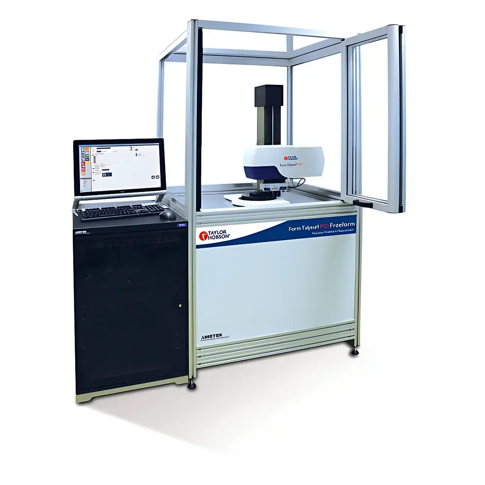
Taylor Hobson PGI Freeform Contact Profilometer
| Brand | Taylor Hobson |
|---|---|
| Origin | United Kingdom |
| Model | PGI Freeform |
| Type | Contact Profilometer / Surface Roughness & Form Measuring System |
| Measurement Principle | Precision Stylus-Based Scanning with Radial and Grid Mapping |
| Vertical Range | 28 mm |
| Vertical Resolution | 0.8 nm |
| Tilt Capability | ±50° |
| Form Error Accuracy | <150 nm PV (as per ISO 5436-1, ISO 25178) |
| Compliance | ASTM E1155, ISO 10360-5, ISO 21920-2, ISO 25178-600 |
Overview
The Taylor Hobson PGI Freeform is a high-precision, contact-based profilometer engineered specifically for the metrology of complex optical and mechanical freeform surfaces. Built upon decades of heritage in stylus-based form measurement and refined through extensive finite element analysis (FEA)-driven mechanical optimization, the system delivers sub-nanometer vertical resolution and exceptional motion fidelity across its linear and rotational axes. Unlike conventional profilometers limited to rotationally symmetric geometries, the PGI Freeform implements synchronized radial and orthogonal grid scanning protocols—enabling full 3D topographic reconstruction of non-rotationally invariant surfaces such as NURBS-defined patches, Zernike-polynomial surfaces, toroidal lenses, biconic optics, and freeform mirrors used in advanced imaging systems, EUV lithography tools, and aerospace-grade optical assemblies. Its measurement architecture complies with core international standards including ISO 5436-1 (profilometer calibration), ISO 25178-600 (areal surface texture terminology), and ISO 10360-5 (CMM verification for form measurement), ensuring traceable, auditable results suitable for ISO/IEC 17025-accredited laboratories.
Key Features
- Stylus-based scanning with 0.8 nm vertical resolution and 28 mm total vertical range—optimized for both macro-form and micro-roughness characterization on the same platform.
- Dual-mode acquisition: radial scanning for axisymmetric features (e.g., aspheres, ellipsoids) and orthogonal grid mapping for fully freeform surfaces (e.g., NURBS, Zernike, point-cloud-derived geometries).
- Mechanically decoupled, low-vibration granite base and FEA-optimized air-bearing carriage ensure thermal stability and minimal dynamic error during long-duration scans.
- ±50° tilt capability enables accurate measurement of steep slopes and off-axis segments common in reflective freeform optics without repositioning or multi-setup alignment.
- Integrated reference sphere calibration routine and traceable artifact verification support GLP/GMP-compliant workflows and FDA 21 CFR Part 11–ready audit trails when paired with certified software configurations.
Sample Compatibility & Compliance
The PGI Freeform accommodates optical substrates ranging from fused silica and CaF₂ to silicon carbide and nickel-phosphorus electroless plating—materials commonly used in high-NA imaging systems and space-borne optics. It supports sample diameters up to 300 mm and thicknesses up to 150 mm, with vacuum chuck and custom kinematic mounting options available. All measurement data adhere to ISO 21920-2 (geometrical product specifications for surface texture) and ASTM E1155 (standard test method for determining floor flatness and levelness). Calibration certificates are issued per UKAS-accredited procedures, and system performance validation follows ISO 10360-5 Annex D for form-measuring instruments.
Software & Data Management
The system operates with Form Talysurf® Metrology Software v8.x, a modular platform supporting ISO-standard surface parameter extraction (Sa, Sq, Sp, Sv, Sz), deviation mapping against CAD models (including STEP AP203/214 and IGES imports), and Zernike decomposition up to 64 terms. Raw scan data are stored in vendor-neutral .STL and .XYZ formats; metadata—including environmental conditions, calibration history, and operator ID—is embedded in XML headers. For regulated environments, optional software modules provide electronic signatures, role-based access control, and 21 CFR Part 11–compliant audit logging with immutable timestamped records.
Applications
- Verification of freeform mirror fabrication for synchrotron beamlines and next-generation telescopes (e.g., ELT M2/M3 segments).
- Process feedback in diamond turning and magnetorheological finishing (MRF) of aspheric lenses for AR/VR waveguides.
- GD&T evaluation of precision-machined turbine blade root profiles and combustion chamber liners.
- Validation of additive-manufactured optical mounts requiring nanoscale form fidelity under thermal cycling.
- Research metrology for diffractive optical elements (DOEs) and meta-optical surface structures where phase-error propagation must be quantified at sub-wavelength levels.
FAQ
Does the PGI Freeform require external vibration isolation?
Yes—optimal performance requires installation on a Class A vibration-isolated granite table or active isolation platform, particularly for measurements below 5 nm RMS noise floor.
Can it measure surfaces with discontinuities or sharp edges?
It supports edge-detection algorithms and programmable lift-off routines to navigate steps up to 5 mm height, though tip radius selection (e.g., 2 µm diamond vs. 12.5 µm tungsten carbide) must be matched to local curvature and material hardness.
Is ISO 17025 accreditation supported out-of-the-box?
While the hardware and base software meet foundational requirements, full accreditation necessitates documented uncertainty budgets, inter-laboratory comparison participation, and site-specific validation per ILAC G8:2022—services available via Taylor Hobson’s Metrology Support Division.
What CAD formats are natively supported for nominal-deviation analysis?
STEP AP203, STEP AP214, IGES, and native Zemax .ZMX files (via optional converter); direct import of NURBS control points and Zernike coefficient sets is also implemented.
How is thermal drift compensated during extended scans?
Real-time temperature monitoring (±0.05°C resolution) feeds into a dynamic compensation model derived from multi-point thermal mapping of the carriage and column—reducing drift-induced form error by >70% over 2-hour acquisitions.