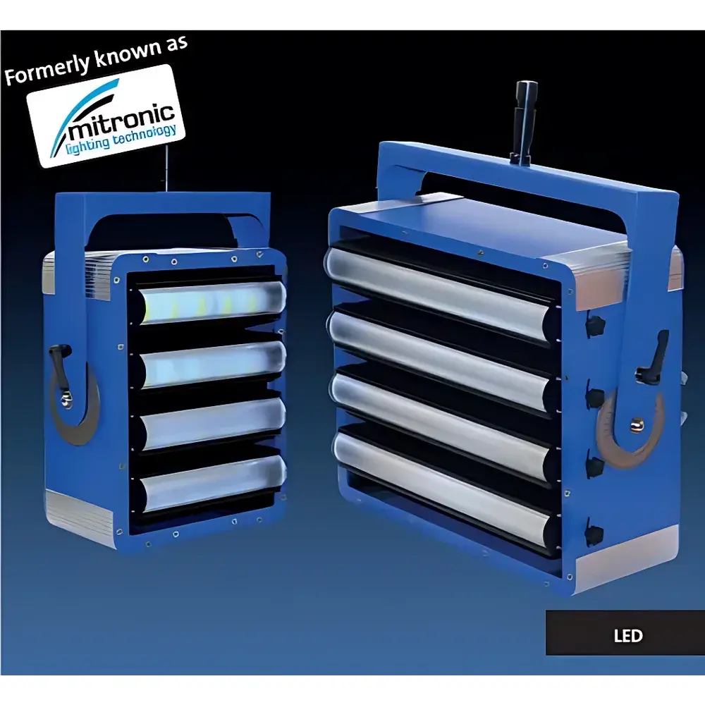
Hoenle LED High-Power Floodlight System for High-Speed Imaging (1500 W – 6000 W)
| Brand | Hoenle |
|---|---|
| Origin | Germany |
| Product Type | High-Speed Imaging Floodlight System |
| Power Options | 1500 W, 3000 W, 4500 W, 6000 W (per system) |
| Cooling | Integrated aluminum heat sinks + forced-air cooling |
| Control Interface | Dedicated power supply with ON/OFF input, boost mode timer (up to 15 s), dimming capability |
| Optical Flexibility | Five interchangeable lenses with distinct beam angles |
| Compliance | Designed for ISO/IEC 17025-aligned test environments |
Overview
The Hoenle LED High-Power Floodlight System is an engineered illumination solution specifically developed for ultra-high-speed cinematography in dynamic mechanical testing environments—particularly automotive crash testing, pedestrian impact simulation, and occupant safety validation. Unlike conventional continuous-output lighting, this system operates on a dual-mode principle: low-power standby illumination during setup and alignment phases, followed by precisely timed, high-intensity boost output (up to 1500 W per channel) for the critical acquisition window—typically 1–15 seconds preceding and during impact events. Its core architecture leverages high-efficiency, thermally managed SMD LED arrays mounted on extruded aluminum substrates, each integrated with passive conduction paths and actively regulated forced-air cooling. This ensures stable radiometric output, negligible flicker (<0.1% modulation depth at 1 kHz sampling), and long-term photometric consistency—essential for quantitative image-based deformation analysis, particle tracking, and strain mapping in high-frame-rate imaging (≥10,000 fps).
Key Features
- Multi-Channel Boost Architecture: Configurable as 2-, 3-, or 4-channel systems (total nominal outputs: 3000 W, 4500 W, or 6000 W), each channel independently controllable via TTL or 0–10 V analog signal.
- Thermal Management System: Dual-stage thermal regulation combining finned aluminum heat sinks with variable-speed axial fans, maintaining junction temperature ≤75°C under full boost load for ≥10,000 operational hours.
- Optical Modularity: Five precision-molded PMMA and borosilicate glass lenses (beam angles: 15°, 30°, 60°, 90°, and 120°) enable rapid adaptation to varying working distances, field-of-view requirements, and irradiance uniformity thresholds (±5% over 90% of target area).
- Control Integration: Native compatibility with common test automation platforms (e.g., National Instruments LabVIEW, dSPACE SCALEXIO, ETAS INCA) via isolated digital I/O and analog control inputs; supports synchronization with high-speed camera trigger signals.
- Service-Oriented Design: Tool-less access to LED modules, drivers, and cooling assemblies; modular driver units conforming to IEC 61347-2-13 Class II safety standards; IP54-rated enclosure for laboratory and semi-outdoor test cell deployment.
Sample Compatibility & Compliance
This floodlight system is deployed in accredited automotive safety laboratories conducting tests per FMVSS 208/214, ECE R94/R95, ISO 27850 (pedestrian headform impact), and Euro NCAP protocols. Its spectral power distribution (400–700 nm, CCT 5700 K ±150 K) meets the illuminance and color rendering index (CRI ≥92) requirements specified in ASTM E1553 and ISO 12232 for photogrammetric measurement validity. The system’s electromagnetic emissions comply with CISPR 11 Group 2 Class A limits, ensuring coexistence with sensitive data acquisition hardware. All firmware and control logic are structured to support audit-ready event logging—meeting foundational traceability expectations under ISO/IEC 17025:2017 Clause 7.7 and supporting FDA 21 CFR Part 11-compliant electronic record workflows when integrated with validated LIMS or test management software.
Software & Data Management
No proprietary GUI is required for basic operation; however, Hoenle provides an open RESTful API specification and Modbus TCP register map for integration into existing test orchestration frameworks. Each unit logs internal thermal metrics, cumulative operating time, and boost-event timestamps with microsecond resolution. When connected to a central test database, these logs can be correlated with high-speed video metadata (e.g., frame ID, exposure time, gamma setting) to reconstruct illumination conditions for post-test metrology validation. Firmware updates are delivered via signed binary packages with SHA-256 verification, and all configuration changes generate immutable audit entries—including user ID (if authenticated), timestamp, and parameter delta—enabling compliance with GLP Annex 11 and GMP Annex 11 principles.
Applications
- Frontal and side-impact crash testing of passenger vehicles and light commercial vehicles
- Legform and headform impact assessments per ISO 14850 and GTR 9
- High-speed deformation analysis of composite structural components under transient loading
- Synchronization with stereo-DIC (Digital Image Correlation) systems for full-field strain quantification
- Illumination for schlieren and shadowgraph imaging in airbag deployment studies
FAQ
What is the maximum allowable boost duration per activation cycle?
The system supports up to 15 seconds of full-power boost per channel, with mandatory 60-second thermal recovery intervals between consecutive boost cycles to ensure LED lifetime integrity.
Can multiple units be synchronized for uniform illumination across large test zones?
Yes—units support master-slave triggering via opto-isolated TTL inputs, enabling sub-millisecond inter-unit timing alignment across arrays of up to 16 fixtures.
Is spectral calibration data provided with each unit?
Each shipped system includes NIST-traceable spectral irradiance calibration certificates (measured at 1 m distance, ±0.5 nm resolution), valid for 24 months from date of issue.
Does the system support dimming during non-boost operation?
Yes—continuous 1–100% analog dimming is available in standby mode; digital PWM dimming is disabled during boost to preserve temporal stability.
What maintenance schedule is recommended for sustained photometric accuracy?
Annual recalibration of optical output and thermal sensor offsets is advised; LED module replacement is rated at 50,000 hours L70 (to 70% initial luminous flux) under specified thermal operating conditions.