Jenoptik C-Series & CS-Series Optical Shaft Measuring Machines
| Brand | Jenoptik |
|---|---|
| Origin | Germany |
| Model | C-Series (C203, C305, C308, C314, C605, C608, C614, C623, C908, C914, C923) / CS-Series (CS155, CS305, CS308, CS314, CS608, CS614, CS908, CS914) |
| Length Measurement Accuracy | (2.6 + L[mm]/200) µm (C-Series), (3.5 + L[mm]/100) µm (CS-Series) |
| Diameter Measurement Accuracy | (1.0 + D[mm]/200) µm (C-Series), (1.3 + D[mm]/100) µm (CS-Series) |
| Max Measurable Length | 250–900 mm |
| Max Measurable Diameter | 30–230 mm |
| Application Scope | Rotating shaft components requiring GD&T-compliant optical metrology |
Overview
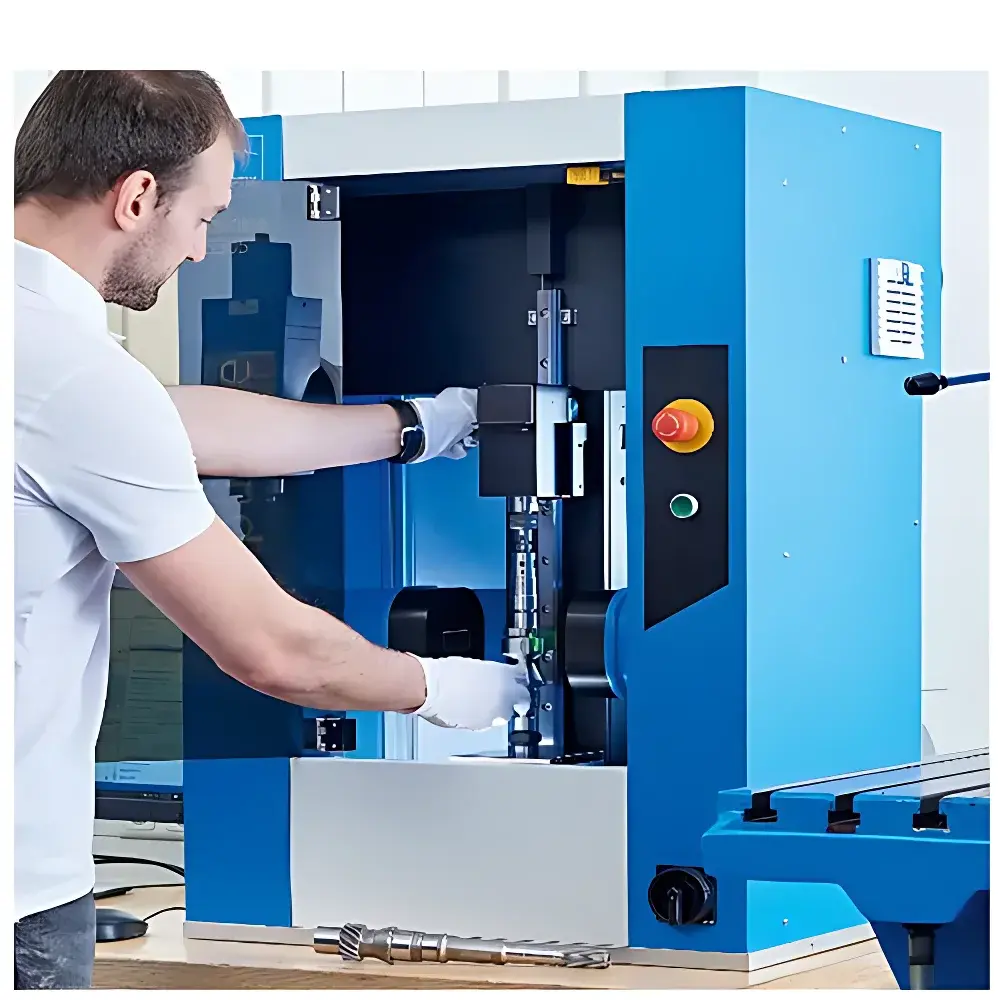
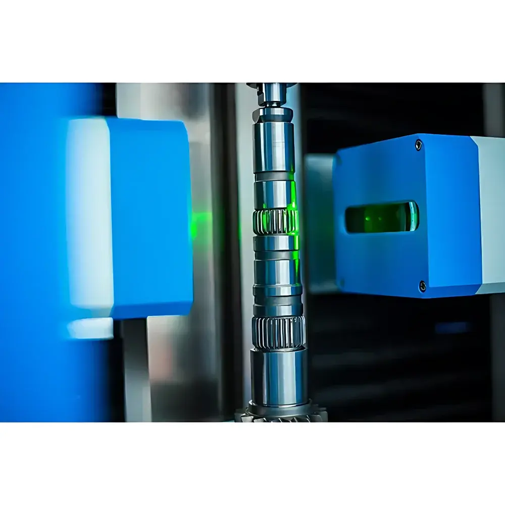
The Jenoptik C-Series and CS-Series Optical Shaft Measuring Machines are high-precision, non-contact coordinate measuring systems engineered specifically for the dimensional and geometric inspection of rotationally symmetric precision shafts. Based on advanced telecentric optical imaging combined with motorized multi-axis motion control and calibrated image-based edge detection algorithms, these instruments perform full-profile metrology without mechanical probing or part contact—preserving surface integrity and eliminating stylus-induced deformation errors. Designed for production-integrated quality assurance environments, the system delivers traceable, ISO 17025-aligned measurement data compliant with ISO 1101 (Geometrical Product Specifications – Geometrical tolerancing), ISO 15530 (Coordinate measuring machines – Calibration of software), and ASME Y14.5 (Dimensioning and Tolerancing). The platform supports both standalone operation in metrology labs and automated integration into Industry 4.0 manufacturing cells via Ethernet/IP and OPC UA interfaces.
Key Features
- Non-contact, high-resolution telecentric optics with sub-micron edge detection resolution across full field-of-view
- Motorized Z-axis translation and rotary stage enabling fully automated multi-angle profile capture and 360° cylindrical evaluation
- Integrated thermal compensation system maintaining measurement stability within ±0.5 µm over ambient fluctuations of ±2 °C
- Dual-mode illumination (backlight + coaxial LED) optimized for edge contrast enhancement on machined, ground, and coated shaft surfaces
- Real-time GD&T calculation engine supporting straightness, roundness, cylindricity, concentricity, coaxiality, radial/axial runout, symmetry, parallelism, and angular deviation per ISO 1101
- Thread analysis module with automatic pitch, flank angle, major/minor diameter, and helix deviation evaluation—including handedness classification (right/left-hand) using directional intensity gradient mapping
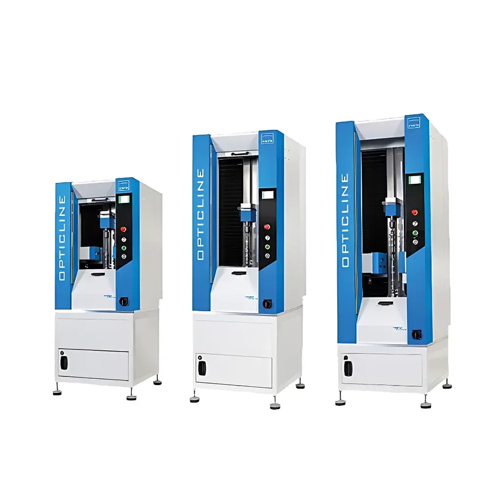
- Modular hardware architecture allowing configuration scalability from compact CS-Series (150–900 mm length range) to high-stability C-Series (up to 230 mm diameter capacity)
Sample Compatibility & Compliance
The system accommodates a broad spectrum of rotationally symmetric industrial components, including crankshafts, camshafts, gear shafts, turbine blades, steering column assemblies, orthopedic bone screws, machine tool spindles, hydraulic valve stems and sleeves, precision bearing rollers, electric motor rotors, pneumatic actuator shafts, power tool mandrels, and threaded fasteners (bolts, studs, and precision screws). All configurations comply with EU Machinery Directive 2006/42/EC, CE marking requirements, and electromagnetic compatibility standards EN 61326-1. Measurement uncertainty budgets are documented per ISO/IEC 17025:2017 Annex A.5 and support GLP/GMP audit readiness when paired with optional 21 CFR Part 11-compliant software modules.
Software & Data Management
Jenoptik’s proprietary ShaftInspect software provides intuitive workflow-driven measurement programming, real-time statistical process control (SPC) dashboards, and automated report generation in PDF, XML, and CSV formats. The software includes built-in calibration routines traceable to national metrology institutes (PTB, NIST), configurable measurement templates aligned with customer-specific drawing callouts, and version-controlled parameter libraries for repeatable setup across shifts and sites. Audit trail functionality records all operator actions, measurement parameters, and result modifications with time stamps and user authentication—fully satisfying FDA 21 CFR Part 11 electronic record/electronic signature (ER/ES) requirements. Data export supports MES/ERP integration via RESTful API and SQL database connectors.
Applications
- Automotive Tier-1 suppliers performing 100% inline verification of camshaft lobe profiles and journal roundness deviations
- Medical device manufacturers validating thread geometry and taper conformity of Class II implant-grade bone fixation screws
- Aerospace subcontractors certifying concentricity and axial runout of turbine shaft assemblies prior to balancing
- Bearing manufacturers assessing roller contour deviation against DIN 5402 tolerance bands
- Hydraulic component producers verifying seat angle and land width consistency on servo-valve spools
- Electric motor OEMs conducting final GD&T validation of rotor shafts prior to magnetization and assembly
FAQ
What standards does the system comply with for geometric tolerance evaluation?
The instrument implements algorithms validated against ISO 1101, ISO 12780 (straightness), ISO 12181 (roundness), ISO 12180 (cylindricity), and ISO 5725 (accuracy of measurement methods).
Can the system measure threads with non-standard pitches or custom flank angles?
Yes—the thread analysis module supports user-defined pitch ranges (0.1–10 mm), variable flank angles (15°–90°), and asymmetric thread forms through programmable profile fitting and deviation mapping.
Is thermal drift compensation available as standard or optional?
Thermal compensation is integrated as standard hardware functionality, utilizing dual-sensor ambient and stage temperature monitoring with real-time correction applied to all axis position feedback loops.
How is measurement traceability maintained across multiple machines in a global facility network?
Each unit ships with a PTB-traceable calibration certificate; inter-machine correlation is ensured via Jenoptik’s Cross-System Validation Kit (CSVK), which includes certified master shafts and standardized alignment protocols per VDI/VDE 2617 Part 7.