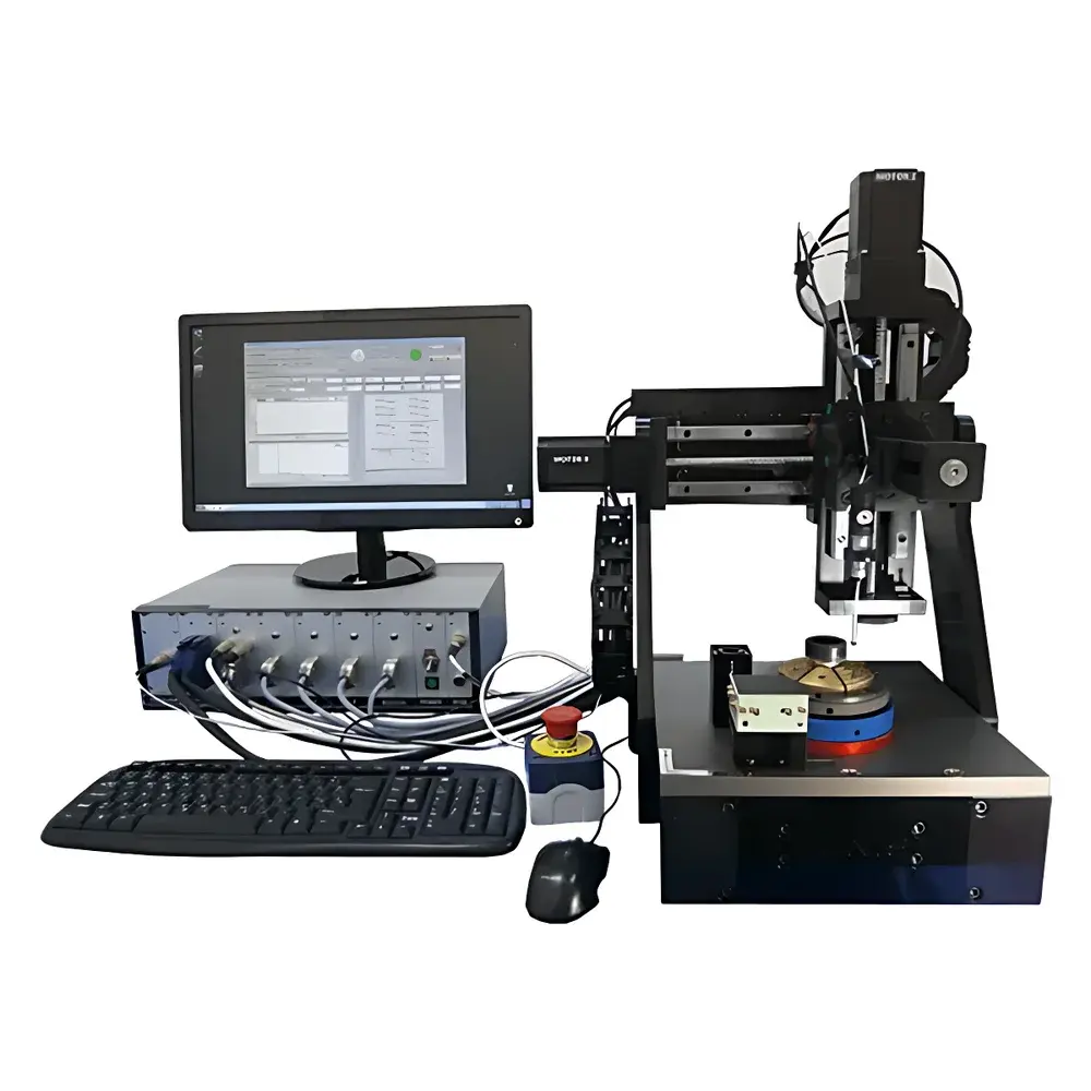
Auniontech MMS-1A-RS 3D Magnetic Field Imaging & Mapping System
| Brand | Auniontech |
|---|---|
| Origin | Shanghai, China |
| Manufacturer Type | Authorized Distributor |
| Product Category | Domestic |
| Model | MMS-1A-RS |
| Measurement Principle | Pulsed and DC/AC Magnetic Field Mapping via Triaxial Hall Probe |
| Scanning Range (X×Y×Z) | Standard 135 mm × 135 mm × 135 mm |
| Spatial Resolution | ≤1 µm (linear), 0.022° (rotational) |
| Field Measurement Ranges | 50 mT / 0.2 T / 1 T or 0.1 T / 0.5 T / 2 T |
| Field Accuracy | Better than ±0.1% of reading |
| Frequency Bandwidth | DC–2.5 kHz (standard triaxial probe) |
| Probe Dimensions (Sensitive Volume) | By: 0.02 × 0.005 × 0.02 mm³ |
| Bx & Bz | 0.14 × 0.01 × 0.14 mm³ |
| Temperature Monitoring | Integrated real-time thermal sensing |
| Motion Control | 4-axis (X/Y/Z linear + θ rotation) with Renishaw TP20 tactile sensor for collision-safe tip positioning |
| Software Platform | Windows-based LabVIEW application with customizable visualization, GLP-compliant data logging, and on-site recalibration capability |
Overview
The Auniontech MMS-1A-RS 3D Magnetic Field Imaging & Mapping System is a precision-engineered instrument designed for quantitative spatial characterization of static (DC) and time-varying (AC) magnetic fields generated by permanent magnets, electromagnetic actuators, rotors, stators, PCBs, and microelectronic assemblies. Operating on the principle of high-fidelity triaxial Hall effect sensing, the system captures vector field components (Bx, By, Bz) simultaneously at each measurement point—enabling true 3D vector field reconstruction without rotational interpolation artifacts. Its integrated 4-axis motion architecture (X/Y/Z translation + high-resolution angular positioning) supports both discrete point-by-point and continuous raster scanning modalities, delivering sub-micrometer positional repeatability and angular resolution down to 0.022°. The system is explicitly engineered for applications demanding traceable field metrology—including magnet quality assurance, rotor pole alignment verification, multi-pole magnet design validation, and failure analysis of magnetized components in production environments.
Key Features
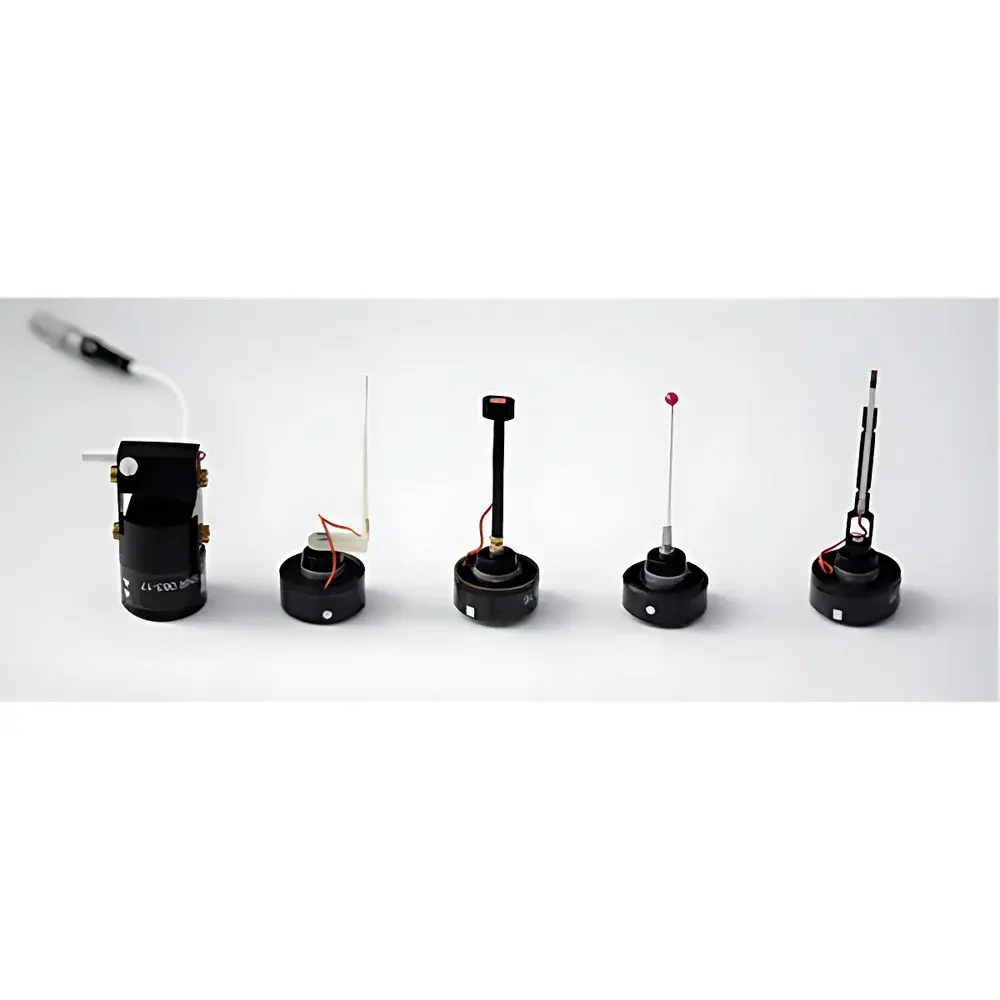
- True simultaneous acquisition of Bx, By, and Bz using a fully integrated CMOS-based triaxial Hall probe with sub-10 µm sensitive volume dimensions.
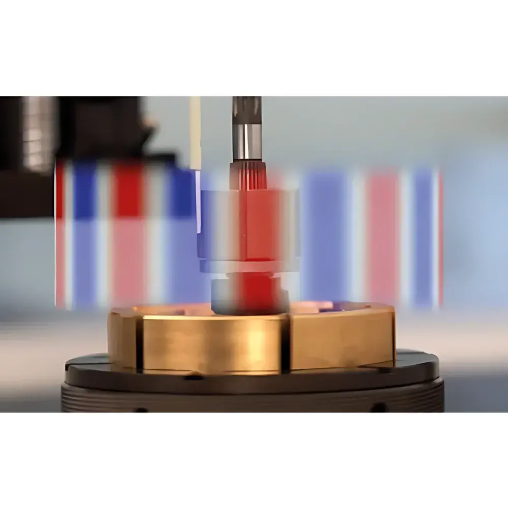
- 4-axis synchronized motion control (X/Y/Z linear stages + precision rotary stage) with Renishaw TP20 tactile trigger sensor for non-destructive probe positioning and mechanical zero detection.
- Configurable field range selection (e.g., 50 mT / 0.2 T / 1 T or 0.1 T / 0.5 T / 2 T) to optimize signal-to-noise ratio across diverse magnet strengths.
- Real-time temperature monitoring co-located with the probe head, enabling thermal drift compensation and correlated thermal-field analysis.
- High-resolution scanning: ≤1 µm linear step resolution, 0.022° angular resolution, and built-in linear encoders for closed-loop positional feedback.
- Expandable bandwidth options: standard DC–2.5 kHz (–3 dB), extendable to 25 kHz (triaxial) or 75 kHz (single-axis) for dynamic field characterization including harmonic content and THD evaluation.
Sample Compatibility & Compliance
The MMS-1A-RS accommodates a broad spectrum of sample geometries—from miniature MEMS-scale magnets and encoder rings to large-diameter motor rotors (up to 500 mm scan envelope option). Its modular multi-jaw rolling chuck ensures stable, concentric clamping of cylindrical components during rotational scanning. All hardware and software modules comply with industrial electromagnetic compatibility (EMC) standards IEC 61326-1 and safety directives per IEC 61010-1. Data acquisition workflows support audit-trail generation and electronic signature capability, aligning with GLP and GMP documentation requirements. While not FDA-cleared as a medical device, its measurement traceability framework is compatible with ISO/IEC 17025-accredited calibration practices when paired with NIST-traceable field standards.
Software & Data Management
Controlled via a native LabVIEW-based application running on Microsoft Windows, the MMS-1A-RS software provides full parametric configuration of scan paths, dwell times, field ranges, and trigger conditions. It delivers real-time 2D color-mapped field projections (Bmag, Bx, By, Bz) and interactive 3D isometric surface plots with user-defined iso-surfaces and vector glyphs. Analytical functions include automatic pole counting, pole width quantification, zero-crossing detection, angular error calculation (e.g., for skewed rotor alignment), harmonic decomposition (FFT up to 2.5 kHz), and pass/fail classification based on user-defined tolerance bands. Raw datasets are stored in HDF5 format with embedded metadata (timestamp, position, temperature, range setting), ensuring long-term reproducibility and interoperability with MATLAB, Python (h5py), or third-party statistical analysis platforms. On-site recalibration routines are accessible without factory intervention.
Applications
- Quality control of sintered NdFeB and ferrite magnets: pole count verification, field uniformity mapping, and crack detection via localized field distortion signatures.
- Rotor and stator validation in BLDC and stepper motors: angular misalignment assessment, pole symmetry analysis, and harmonic content evaluation for torque ripple prediction.
- PCB-level EMI diagnostics: near-field magnetic emission mapping around power converters, inductors, and high-speed digital traces.
- Development of magnetic encoders and position sensors: spatial field gradient characterization and linearity error quantification.
- Research in magneto-optical materials and spintronic devices: localized field profiling under controlled thermal or bias conditions.
- Automated inspection integration: configurable pass/fail logic enables deployment in inline manufacturing test stations with PLC interface support.
FAQ
What magnetic field strength ranges does the MMS-1A-RS support?
The system offers two configurable range sets: 50 mT / 0.2 T / 1 T or 0.1 T / 0.5 T / 2 T—selected automatically or manually depending on expected field magnitude.
Can the system measure AC magnetic fields?
Yes—standard configuration supports DC to 2.5 kHz (–3 dB). Optional probes extend bandwidth to 25 kHz (triaxial) or 75 kHz (single-axis) for high-frequency transient or PWM-driven field analysis.
Is on-site recalibration possible?
Yes—the software includes guided procedures for user-performed probe sensitivity and offset recalibration using certified reference magnets or Helmholtz coil sources.
Does the system meet regulatory requirements for production use?
It supports GLP/GMP-aligned data integrity features including audit trails, electronic signatures, and version-controlled measurement protocols—though formal validation must be performed per site-specific SOPs.
What sample sizes can be accommodated?
Standard scan volume is 135 mm × 135 mm × 135 mm; optional extended gantry supports samples up to 500 mm × 500 mm × 135 mm, with custom fixtures available for oversized rotors or stators.
Related Products


