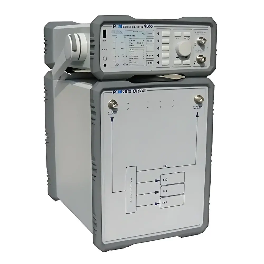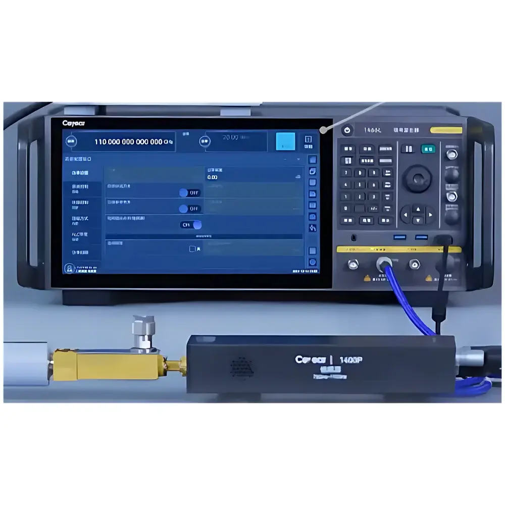
Auniontech 60–170 GHz Analog Signal Generator Multiplier Source
| Brand | Auniontech |
|---|---|
| Origin | Shanghai, China |
| Model | Multiplier Source for Analog Signal Generators |
| Frequency Range | 60–170 GHz |
| Input Drive Frequency | < 20 GHz |
| Open-Loop Output Power | ≥ +17 dBm (60–110 GHz), ≥ +15 dBm (110–170 GHz) |
| Power Stabilization Dynamic Range | ≥ 34 dB (60–110 GHz), ≥ 30 dB (110–170 GHz) |
| Spurious Suppression | ≥ 40 dBc |
| Form Factor | Compact, Low-Profile “Sunken” RF Output Port |
| Control Interface | USB |
Overview
The Auniontech 60–170 GHz Analog Signal Generator Multiplier Source is a precision frequency extension module engineered to extend the operational bandwidth of standard analog signal generators into the E-band and W-band millimeter-wave spectrum. Unlike broadband synthesizers or VNA-based sources, this multiplier source operates on harmonic generation principles—accepting a fundamental input signal below 20 GHz and producing coherent, phase-preserving harmonics up to the 8th or 9th order—enabling accurate, low-phase-noise analog waveform synthesis from 60 GHz through 170 GHz. It is designed for integration into automated test systems where high-frequency signal fidelity, rapid power-state switching, and repeatable amplitude control are critical—particularly in on-wafer RF characterization, 5G/6G component validation, radar cross-section simulation, and terahertz spectroscopy pre-staging.
Key Features
- Wideband coverage across two contiguous bands: 60–110 GHz and 110–170 GHz, supporting both E-band (60–90 GHz) and W-band (75–110 GHz, 110–170 GHz) applications.
- High open-loop output power: ≥ +17 dBm over 60–110 GHz and ≥ +15 dBm over 110–170 GHz—enabling direct drive of passive mixers, Schottky diode detectors, and waveguide components without external amplification.
- Dual-mode operation: configurable via USB command set between open-loop (saturation-driven, maximum power) and closed-loop (stabilized amplitude) modes—eliminating manual mechanical attenuator adjustments and reducing setup time by >70% in production test environments.
- Exceptional spectral purity: in-band spurious suppression ≥ 40 dBc ensures minimal interference with adjacent channels—critical for compliance testing per IEEE 802.15.3d, 3GPP TR 38.812, and ITU-R F.2400-0.
- Compact, low-profile mechanical design featuring a recessed (“sunken”) 1.0 mm or UG-387 waveguide output interface—optimized for probe station integration, coplanar waveguide alignment, and space-constrained RF shielding enclosures.
- USB 2.0 host interface with SCPI-compatible command set for seamless integration into LabVIEW, Python (PyVISA), MATLAB, and Keysight PathWave environments—supporting remote configuration of frequency sub-bands, output enable/disable, and real-time power calibration offsets.
Sample Compatibility & Compliance
The multiplier source is compatible with industry-standard analog signal generators delivering ≤ +18 dBm at frequencies < 20 GHz—including Keysight MXG/EXG series, Rohde & Schwarz SMB/SMA100B, and Anritsu MG3700E platforms. Its RF output meets WR-15 (60–90 GHz), WR-12 (60–110 GHz), and WR-06 (110–170 GHz) waveguide interface specifications per IEEE 1785.1. All units undergo factory calibration traceable to NIM (National Institute of Metrology, China) standards. The device supports GLP-compliant operation when used with calibrated signal generators and is suitable for ISO/IEC 17025-accredited laboratories performing RF component verification under IEC 62047-21 (MMIC testing) and MIL-STD-461G radiated emission pre-scan protocols.
Software & Data Management
Firmware supports SCPI command syntax over USB virtual COM port, enabling full programmability without proprietary drivers. Calibration data—including power vs. frequency correction tables and harmonic suppression profiles—is stored onboard and automatically applied during amplitude stabilization. Software development kits (SDKs) are provided for Windows/Linux in C/C++, Python, and .NET—featuring built-in interpolation routines for smooth power ramping and event-triggered mode switching. Audit trails for all power and mode changes can be logged to CSV or HDF5 format, satisfying FDA 21 CFR Part 11 requirements when deployed in regulated R&D environments.
Applications
- On-wafer S-parameter measurement of GaN HEMT and SiGe HBT devices using vector network analyzers equipped with harmonic mixer receivers.
- Millimeter-wave antenna pattern measurement in compact range facilities requiring stable, tunable CW sources with fast amplitude settling (< 10 ms).
- Calibration of wideband millimeter-wave receivers used in satellite communication ground terminals operating in Q/V/E/W bands.
- Local oscillator (LO) sourcing for heterodyne radiometers and atmospheric remote sensing instruments targeting O2 and H2O absorption lines near 60 GHz and 118 GHz.
- EMI/EMC pre-compliance testing of high-speed digital interconnects (e.g., PCIe 6.0, USB4 Gen 4) where radiated emissions above 100 GHz must be characterized.
FAQ
What input signal level and spectral purity are required for optimal harmonic generation?
A fundamental input of +13 to +18 dBm with phase noise ≤ –110 dBc/Hz at 10 kHz offset (at 10 GHz) is recommended to maintain spurious suppression ≥ 40 dBc and minimize AM-to-PM conversion.
Can the multiplier source operate without an external signal generator?
No—it is a passive multiplier module requiring a clean, amplified fundamental tone; it contains no internal oscillator or synthesizer.
Is waveguide flange type specified per band?
Yes: WR-15 (60–90 GHz), WR-12 (90–110 GHz), and WR-06 (110–170 GHz) flanges are available—custom flange adapters (e.g., V-band to WR-12) may be ordered separately.
Does the unit support external power leveling via feedback loop?
No—amplitude stabilization is achieved via internal RMS-detected closed-loop control; external power meter feedback is not supported but can be implemented at system level using SCPI polling.
What is the typical warm-up time to achieve amplitude stability within ±0.1 dB?
Less than 90 seconds after power-on, assuming ambient temperature variation < ±2 °C.