quTools quDIS Picometer-Accuracy Displacement Laser Interferometer
| Brand | quTools |
|---|---|
| Origin | Germany |
| Model | quDIS |
| Measurement Principle | Dual-Reference Laser Interferometry with Fabry–Pérot Cavity and Gas Cell (GC) Frequency Stabilization |
| Resolution | 1 pm |
| Relative Distance Stability | < 0.05 nm |
| Absolute Distance Accuracy | < 0.2 nm/mm |
| Wavelength | 1535 nm |
| Linewidth | < 5 MHz |
| Bandwidth | 25 kHz |
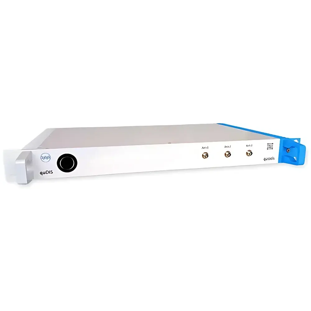
| Number of Measurement Channels | 3 |
| Working Distance | 0.1–20 m (sensor-head dependent) |
| Maximum Target Velocity | 1 m/s |
| Laser Output Power | < 400 µW |
| Input Fiber Connector | FC Narrow-Key-Slot |
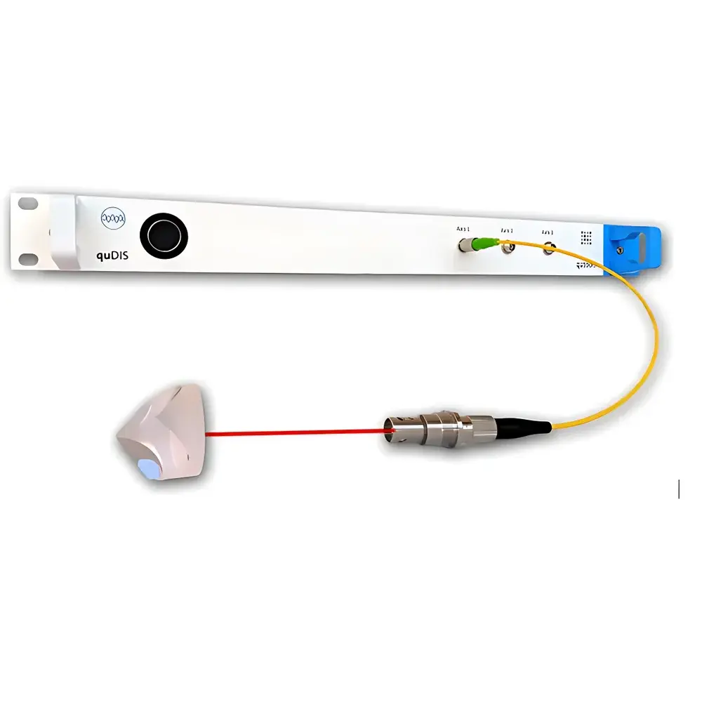
| Sensor Head Options | Collimated, Focused, Low-CTE (Invar/NiFe), High-Temp, Vacuum-Grade |
Overview
The quTools quDIS Picometer-Accuracy Displacement Laser Interferometer is a high-precision metrology instrument engineered for sub-nanometer displacement measurement in research-grade and industrial metrology environments. Unlike conventional homodyne or heterodyne interferometers relying solely on fringe counting or phase interpolation, the quDIS implements a dual-reference frequency-stabilized interferometric architecture. It integrates a thermally stabilized Fabry–Pérot cavity and a saturated-absorption gas cell (GC) to serve as absolute wavelength references. By scanning the DFB laser diode across its emission band and comparing interference fringes from both references, the system reconstructs optical path difference with traceable SI-unit linkage—enabling true absolute distance measurement without reliance on mechanical encoders or periodic calibration artifacts. This methodology eliminates cyclic nonlinearity, cosine error, and intensity-dependent signal distortion commonly observed in traditional Michelson or Mach–Zehnder configurations. The quDIS achieves a demonstrated relative displacement stability of < 0.05 nm RMS over hours and an absolute accuracy of < 0.2 nm per mm of measured distance—validated against NIST-traceable step gauges and primary length standards.
Key Features
- Picometer-level resolution (1 pm) with real-time digital output at up to 25 kHz bandwidth
- Three independent interferometric channels for simultaneous multi-axis displacement monitoring
- Dual-reference stabilization: integrated Fabry–Pérot cavity + saturated-absorption gas cell for long-term wavelength fidelity
- Fiber-coupled architecture with FC narrow-key-slot interface; compatible with vacuum, cryogenic, and high-vibration environments
- Modular sensor head design: collimated, focused, low-thermal-expansion (Invar/NiFe), vacuum-rated, and high-temperature variants available
- No inherent nonlinearity—displacement extraction uses full interference pattern analysis, not zero-crossing detection
- Robust operation over 0.1–20 m working distance; target velocity support up to 1 m/s
- Simultaneous acquisition of position, velocity, acceleration, surface tilt, reflectivity, and local refractive index variations
Sample Compatibility & Compliance
The quDIS is designed for compatibility with diverse optical targets—including polished metals, dielectric coatings, silicon wafers, and MEMS structures—without requiring retroreflective optics. Its fiber-delivered 1535 nm beam minimizes atmospheric dispersion and water vapor absorption, enabling stable operation in ambient air, dry nitrogen purged enclosures, or high-vacuum chambers (<10⁻⁶ mbar). All sensor heads meet ISO 10110 surface quality specifications and are rated for continuous operation between –40 °C and +85 °C. The system complies with electromagnetic compatibility requirements per EN 61326-1:2013 and safety standards per IEC 61010-1:2010. For regulated environments, firmware supports audit-trail logging and user-access control aligned with FDA 21 CFR Part 11 principles—facilitating GLP/GMP-compliant deployment in semiconductor fab metrology, gravitational wave detector alignment, and synchrotron beamline positioning.
Software & Data Management
The quDIS ships with quCONTROL—a cross-platform application (Windows/Linux) supporting real-time visualization, multi-channel time-series export (HDF5, CSV), FFT-based vibration spectrum analysis, and automated drift compensation algorithms. APIs (C/C++, Python, LabVIEW) enable integration into custom automation frameworks and PLC-controlled motion systems. Raw interferogram data is timestamped with IEEE 1588 PTP synchronization capability, allowing sub-microsecond alignment across distributed quDIS units. Data integrity is preserved via checksummed binary streaming and optional encrypted storage. Calibration certificates include uncertainty budgets traceable to PTB (Physikalisch-Technische Bundesanstalt) reference interferometers.
Applications
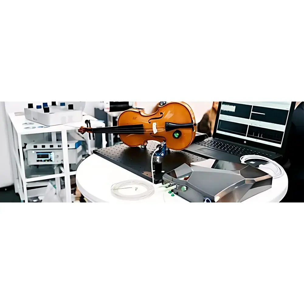
- Thermal drift characterization of optical benches, lithography stages, and telescope mirror mounts
- Vibration mode analysis of aerospace components under environmental stress screening
- Real-time feedback for active stabilization of atomic force microscope (AFM) scanners and nanopositioning piezo stages
- In-situ gap monitoring in multilayer thin-film deposition chambers
- Dynamic calibration of coordinate measuring machines (CMMs) and laser trackers
- Gravitational reference frame studies requiring picometer-level displacement sensitivity over meter-scale baselines
- Long-term stability validation of quantum sensor platforms (e.g., atom interferometers)
FAQ
Does the quDIS require periodic recalibration?
No—its dual-reference architecture provides intrinsic wavelength stability. Annual verification against a certified length standard is recommended for ISO/IEC 17025 compliance, but no field recalibration is needed.
Can the quDIS operate inside a vacuum chamber?
Yes—vacuum-compatible sensor heads (KF40/CF100 flange options) and hermetically sealed fiber feedthroughs are available. Operating pressure range: 10⁻⁷ mbar to atmospheric.
Is multi-unit synchronization supported?
Yes—via external TTL trigger input or IEEE 1588 Precision Time Protocol (PTP) over Ethernet, enabling sub-100 ns timing alignment across ≥8 quDIS units.
What is the minimum measurable displacement?
The system resolves displacements down to 1 pm RMS within its 25 kHz bandwidth. Sub-picometer detection is achievable through averaging in low-noise, static conditions.
How does the quDIS handle low-reflectivity surfaces?
Signal processing leverages full-fringe contrast analysis rather than peak detection, maintaining accuracy down to ~3% surface reflectivity (e.g., bare silicon at 1535 nm). Optional high-sensitivity photoreceivers further extend dynamic range.