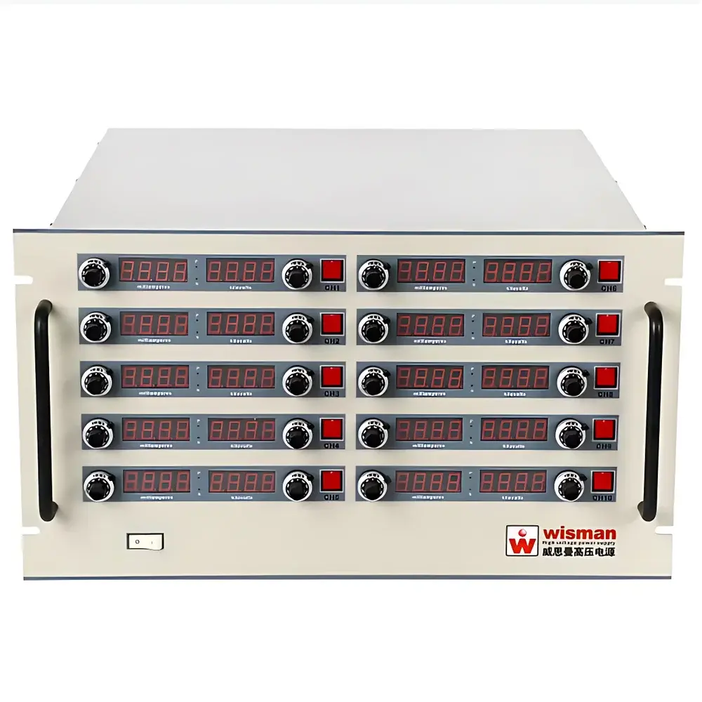
Wisman MS Series 10-Channel High-Voltage Power Supply System — 70 kV / 1200 W Total Output
| Key | Brand: Wisman |
|---|---|
| Origin | Shaanxi, China |
| Form Factor | 19″ Rack-Mount (6U) |
| Channels | 10 Independent |
| Max. Voltage per Channel | 1–70 kV |
| Max. Power per Channel | 100 W |
| Total Rated Power | 1200 W |
| Input | AC 220 V ±10%, 50/60 Hz |
| Output Ripple | 0.1% P-P (customizable lower) |
| Voltage Stability | ≤100 ppm/h, ≤500 ppm/8 h |
| Temp. Coefficient | ≤25 ppm/°C |
| Control Interface | Local (front-panel potentiometers + 4-digit LED displays) & Remote (RS-485) |
| Protections | OVP, OCP, SCP, Arc Detection, Overtemperature, Safety Interlock |
| Compliance | Designed for GLP/GMP-aligned lab environments |
Overview
The Wisman MS Series is a precision-engineered, 10-channel high-voltage DC power supply system designed for demanding scientific and industrial applications requiring stable, independently controllable HV outputs up to 70 kV per channel. Built to 19″ rack-mount standards (6U height), the MS platform employs zero-current resonant switching topology and advanced high-voltage insulation design to achieve low electromagnetic interference, high efficiency (≥85%), and exceptional long-term stability. Each channel operates autonomously—supporting independent voltage/current setpoints, real-time monitoring, and hardware-level protection logic—making it ideal for multi-electrode experiments, parallel ion beam conditioning, or distributed electrostatic process control. Unlike single-output HV supplies, the MS architecture eliminates inter-channel coupling, ensuring measurement integrity in applications such as time-resolved mass spectrometry detector biasing, multi-anode X-ray tube arrays, or synchronized electrospinning nozzles.
Key Features
- 10 fully isolated output channels, each configurable from 0 V to user-specified maximum (1–70 kV); no cross-talk or shared regulation path
- Independent front-panel control per channel: dual 4-digit LED displays (voltage & current), multi-turn potentiometers for analog adjustment
- Digital remote operation via RS-485 interface compliant with Modbus RTU protocol; full readback of actual output values, status flags, and fault logs
- Sub-100 ppm/h short-term stability and ≤500 ppm/8 h long-term drift—validated after 30-minute thermal stabilization at 25 °C ambient
- Low-noise performance: 0.1% peak-to-peak ripple (measured across full load range); optional ultra-low ripple variants available (<0.02% P-P)
- Comprehensive hardware protection suite: overvoltage lockout (OVP), overcurrent shutdown (OCP), short-circuit recovery, arc detection with <10 µs response, thermal cutoff, and safety interlock circuitry meeting IEC 61010-1 Class I requirements
- High power factor (0.995) and wide input tolerance (AC 220 V ±10%; 110 V option available) ensure reliable operation in variable utility conditions
Sample Compatibility & Compliance
The MS Series is routinely deployed as bias supply for time-of-flight mass spectrometers (TOF-MS), electron multipliers, microchannel plates (MCPs), and segmented anode detectors where channel-to-channel isolation prevents signal crosstalk during transient events. Its fast-recovery arc handling enables robust operation in vacuum systems subject to occasional flashover—critical for ion implantation chambers and accelerator beamlines. The unit conforms to electromagnetic compatibility (EMC) limits per CISPR 11 Group 2, Class B, and meets safety requirements under IEC 61010-1 for laboratory electrical equipment. While not certified to FDA 21 CFR Part 11 out-of-the-box, its deterministic RS-485 command-response behavior, non-volatile parameter storage, and hardware-enforced safety states support integration into Part 11–compliant workflows when paired with validated host software and procedural controls.
Software & Data Management
Remote control is implemented through ASCII-based RS-485 commands (Modbus RTU optional), enabling integration with LabVIEW, Python (PySerial), MATLAB, or custom SCADA platforms. Each channel exposes registers for setpoint voltage/current, measured output, status bits (e.g., “Arc Active”, “OVP Latched”), and cumulative fault counters. All parameters are retained in non-volatile memory across power cycles. For regulated environments, users may implement audit trails by logging timestamped command sequences and corresponding register reads on the host side. Firmware updates are performed via UART bootloader—no field-accessible firmware modification is possible without physical serial access and authentication handshake.
Applications
- Mass spectrometry: Detector biasing (MCP, discrete dynode), lens array control, reflectron gating
- Particle acceleration: Electrostatic lens trains, einzel lens stacks, beam steering electrodes
- Materials processing: Electrospinning (multi-nozzle arrays), electrostatic spraying/plating, corona charging of dielectrics
- Imaging & diagnostics: Multi-anode X-ray tube bias, digital radiography detector grids, electron beam lithography columns
- Research infrastructure: Plasma confinement electrode biasing, laser-triggered discharge studies, insulator aging test benches
- Industrial QA: High-potential insulation testing (IEC 60204-1), ESD simulator calibration, corona treatment system validation
FAQ
What is the minimum controllable output voltage?
The output is continuously adjustable from 0 V to the configured maximum per channel. Below 5% of rated voltage, specifications such as ripple and line regulation are relaxed per datasheet tolerances.
Can different channels operate at different voltage levels simultaneously?
Yes—each channel has independent voltage and current setpoints, with no shared regulation or feedback path.
Is analog voltage control supported?
No native 0–10 V analog interface is provided; control is digital (RS-485) or local (front-panel potentiometers). Analog input can be added via external DAC module upon request.
How is arc recovery handled?
Upon arc detection, output is disabled within <10 µs, followed by automatic soft-start re-engagement after programmable delay (default 100 ms); latched faults require manual reset.
What mechanical mounting options are available?
Standard 19″ rack-mount (6U × 19″ W × 24″ D); custom chassis or DIN-rail variants available under OEM agreement.
Does the system support synchronization across channels?
Hardware-triggered simultaneous start/stop is not built-in, but precise timing coordination (<1 ms jitter) is achievable via synchronized RS-485 command bursts from a master controller.


