Wiseman MB Series 3 kV / 2 W Dual-Output High-Voltage DC/DC Module Power Supply
| Brand | Wiseman |
|---|---|
| Model | MB |
| Output Voltage | ±0–3 kV (configurable dual-polarity) |
| Output Power | 2 W (total) |
| Ripple & Noise | <0.08% p-p |
| Stability | 0.001% per hour |
| Temp. Coefficient | 25 ppm/°C |
| Input Voltage | 12 V ±0.5 V (optional: 5 V, 15 V, 24 V) |
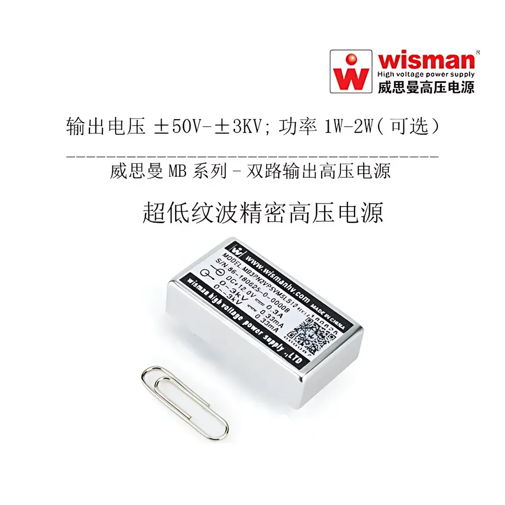
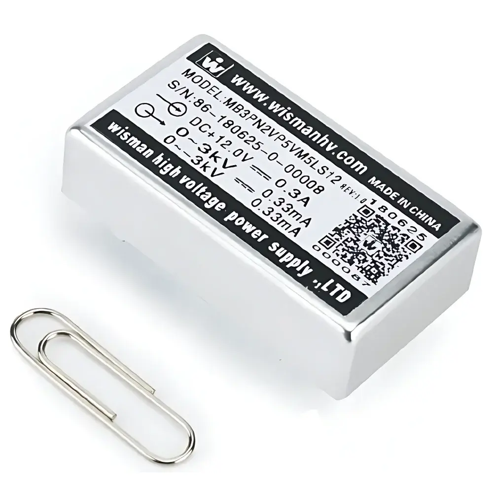
| Dimensions | 45.5 × 25 × 12 mm |
| Weight | 25 g |
| Shielding | Full 6-side electromagnetic shielding |
| Protection | Reverse polarity, overcurrent, short-circuit, arc suppression |
| Operating Temp. | –10°C to +50°C (commercial grade) |
| Compliance | Designed for OEM integration in analytical instrumentation requiring low-noise, high-stability bias supplies |
Overview
The Wiseman MB Series is a compact, PCB-mountable high-voltage DC/DC module engineered specifically for precision biasing applications in scientific instrumentation. Based on zero-current resonant topology and proprietary high-voltage insulation design, the MB module delivers tightly regulated dual-output high voltage with exceptional stability and ultra-low electromagnetic interference. Its core architecture supports configurable polarity combinations — including dual positive, dual negative, or complementary ±3 kV outputs — all within a single 25 g footprint. Unlike general-purpose HV supplies, the MB is optimized for signal integrity-critical subsystems such as photomultiplier tube (PMT) dynode chains, mass spectrometer detector arrays, electron multiplier biasing, and electrostatic lens control. The module operates from a single low-voltage DC input (standard 12 V ±0.5 V), eliminating the need for external AC-DC conversion stages and reducing system-level noise coupling. Its design adheres to fundamental requirements of analytical instrument OEMs: minimal thermal drift, sub-ppm-level long-term stability, and immunity to transient load disturbances typical in pulsed detection environments.
Key Features
- Dual independent high-voltage outputs, each programmable from 0 to ±3 kV with polarity-selectable configuration (M1: ±3 kV; M2: +3 kV/+3 kV; M3: –3 kV/–3 kV)
- Total output power up to 2 W with individual channel derating for thermal management
- Ultra-low output ripple and noise: <0.08% peak-to-peak under full load, achieved via six-sided mu-metal and conductive polymer shielding
- High stability specification: ≤0.001% per hour (typical), supported by temperature-compensated feedback networks
- Low thermal coefficient: 25 ppm/°C across operating range, validated per IEC 61000-4-2 for thermal stress resilience
- Comprehensive protection suite: reverse-input polarity safeguard, overcurrent limiting, hard short-circuit recovery, and arc-detection circuitry with auto-reset
- Analog voltage control interface (0–2.5 V @ 5 V supply) and potentiometer-based setpoint adjustment (20 kΩ ±2.5 kΩ)
- PCB through-hole or surface-mount compatible footprint (45.5 × 25 × 12 mm), enabling direct integration into detector subassemblies
- Input voltage flexibility: standard 12 V ±0.5 V; optional 5 V, 15 V, or 24 V variants available for system-level power architecture alignment
- OEM-customizable options include extended temperature grading (industrial G-grade: –25°C to +65°C; tactical T-grade: –40°C to +95°C), conformal coating, and pinout modifications
Sample Compatibility & Compliance
The MB module is routinely integrated into detector bias rails where microampere-level current stability and nanosecond-scale voltage settling are mandatory. It meets mechanical and electrical interface requirements for OEM integration into mass spectrometry systems compliant with ASTM E1597 (mass spectrometer performance verification) and IEC 61010-1 (safety requirements for electrical equipment). While not certified as a standalone medical device, its design principles align with FDA 21 CFR Part 11 data integrity expectations when embedded in GLP/GMP-regulated instruments — particularly regarding traceable voltage setpoint logging and hardware-enforced fault isolation. The module’s low EMI profile supports compliance with CISPR 11 Class B emission limits when installed with proper grounding and layout practices. No internal battery or wireless components are present, simplifying regulatory pathway for Class I equipment classification.
Software & Data Management
As a hardware-level bias supply, the MB operates without embedded firmware or digital communication interfaces. Voltage setpoints are controlled exclusively via analog signals, ensuring deterministic response timing and eliminating software-induced latency or watchdog dependencies. For systems requiring audit-trail capability, external DAQ modules (e.g., National Instruments PXIe-6363 or Keysight 34972A) may log control voltage inputs and monitor output current telemetry via shunt resistor feedback. When deployed in automated test environments, the MB’s predictable line/load regulation (0.001% and 0.5%, respectively) enables repeatable calibration traceability per ISO/IEC 17025 clause 5.10. Optional OEM firmware integration kits provide reference schematics for closed-loop voltage monitoring using external ADCs and FPGA-based PID controllers.
Applications
- Photomultiplier tube (PMT) dynode chain biasing in scintillation detectors and fluorescence spectrometers
- Electron multiplier and discrete-dynode detector biasing in time-of-flight (TOF) and quadrupole mass spectrometers
- Electrostatic lens and deflector voltage sources in SEM, TEM, and focused ion beam (FIB) platforms
- High-voltage bias for ionization chambers, proportional counters, and Geiger-Müller tubes in radiation measurement systems
- Electrophoresis buffer voltage control in capillary and gel electrophoresis instruments
- Beam steering and blanking electrodes in electron beam lithography tools
- OEM subsystems requiring compact, low-noise HV bias in portable X-ray fluorescence (XRF) analyzers and handheld Raman spectrometers
FAQ
What input voltage options are available for the MB series?
Standard input is 12 V ±0.5 V DC; optional configurations support 5 V ±1 V, 15 V ±1 V, or 24 V ±1 V inputs — specified at time of order.
Can both outputs operate simultaneously at ±3 kV?
Yes — Mode M1 enables one channel at +3 kV and the other at –3 kV, with total output power limited to 2 W combined.
Is remote sensing supported for load regulation compensation?
No — the MB uses local feedback only; for applications requiring remote sense, an external op-amp compensation network must be implemented at the load point.
Does the module comply with RoHS and REACH directives?
Yes — all production units shipped after January 2023 meet RoHS 3 (EU Directive 2015/863) and REACH SVHC thresholds.
What is the mean time between failures (MTBF) under nominal operating conditions?
Based on Telcordia SR-332 Issue 3 methodology, MTBF exceeds 250,000 hours at 25°C ambient, with derating applied above 40°C case temperature.


