Incoatec Synchrotron Optics – High-Performance X-ray Optical Components for Synchrotron and FEL Beamlines
| Brand | Incoatec |
|---|---|
| Origin | Germany |
| Product Type | Optical Component |
| Model | Synchrotron Optics |
| Substrate Material | Si (uncoated & coated) |
| Coating Materials | C, Ru/C, W/Si, Mo/B₄C, and custom multilayer systems |
| Coating Thickness Control Accuracy | ±1% |
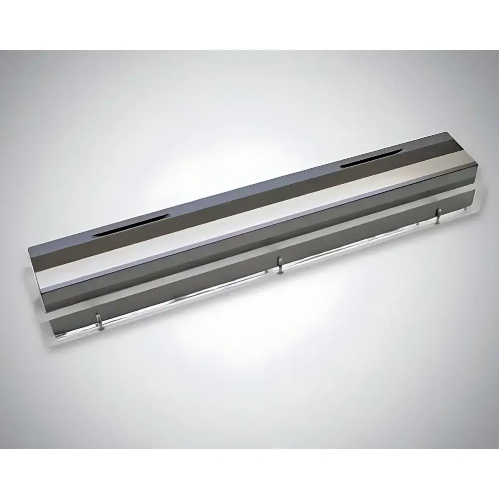
| Maximum Mirror Length | 150 cm |
| Carbon Mirror Thickness | 35 nm (C), 44.2 nm (C) |
| Multilayer Period | 1.4 nm (Mo/B₄C), 2.0 nm (Ru/C), 1.5 nm (W/Si) |
| Energy Range Coverage | 50 eV – 45 keV |
| Reflectivity (C mirror, 50–250 eV) | >95% |
| Thickness Uniformity (across 150 cm) | <2% PV, <0.1% RMS gradient control |
| Compliance | Designed for ISO/IEC 17025-aligned calibration environments, compatible with GLP/GMP beamline operation frameworks |
Overview
Incoatec Synchrotron Optics represents a class of precision-engineered X-ray optical components specifically developed for demanding synchrotron radiation and free-electron laser (FEL) beamline applications. These components operate across an exceptionally broad photon energy range—from the extreme ultraviolet (XUV) at 50 eV up to hard X-ray energies of 45 keV—enabling high-fidelity manipulation of coherent, high-brightness beams in advanced light sources such as DESY’s FLASH and European XFEL, PSI’s Swiss Light Source (SLS), and ESRF-EBS. The core optical principles leveraged include total external reflection (for grazing-incidence mirrors) and Bragg diffraction (for multilayer monochromators and focusing elements), both critically dependent on nanoscale interfacial control, atomic-level layer uniformity, and radiation-hard material selection. Unlike conventional optical coatings, these components are fabricated under ultra-high vacuum (UHV) conditions using magnetron sputtering—a process optimized for sub-ångström thickness reproducibility and minimized interdiffusion at heterointerfaces.
Key Features
- Grazing-incidence carbon-coated silicon mirrors with 35 nm C layers achieving >95% reflectivity across 50–250 eV—performance validated against diamond-like theoretical models (ρ = 3.5 g/cm³).
- Custom multilayer stacks including Ru/C (d-spacing = 2.0 nm), W/Si (d-spacing = 1.5 nm), and Mo/B₄C (d-spacing = 1.4 nm), each engineered for specific Bragg-critical energy bands (e.g., 10–22 keV and 22–45 keV).
- Scalable substrate geometry: uncoated and coated Si substrates available up to 150 cm in length, with surface flatness maintained to λ/10 over full aperture (measured via ex-situ interferometry).
- Atomic-layer thickness control: deposition accuracy better than ±1% per monolayer; thickness uniformity <0.1% RMS across linear gradients; peak-to-valley variation <1 nm over 150 cm for 44.2 nm C films.
- Radiation-resilient architecture: low-Z elemental coatings (C, B, Si) minimize absorption-induced thermal load and damage accumulation under pulsed FEL irradiation (peak fluence >10 mJ/cm²/pulse).
Sample Compatibility & Compliance
These optics are fully compatible with UHV-compatible beamline instrumentation operating at pressures ≤1×10⁻⁹ mbar. Substrates meet SEMI Standard F47-0304 for silicon wafer flatness and particulate cleanliness. All multilayer architectures undergo cross-sectional TEM validation (as documented for Mo/B₄C stacks with 500 bilayers) to verify interface sharpness, crystallinity, and absence of interdiffusion zones exceeding 0.3 nm. Components are supplied with traceable metrology reports—including spectral reflectance curves (measured at BESSY II and SLS), surface roughness (AFM, RMS <0.2 nm over 10×10 µm), and layer-thickness maps—supporting ISO/IEC 17025-compliant calibration workflows. While not certified devices per se, their design and documentation framework aligns with GLP and GMP beamline operational requirements, including audit-ready fabrication logs and material lot traceability.
Software & Data Management
Incoatec provides comprehensive optical simulation support via integration-ready files for standard ray-tracing platforms including SHADOW, XOP, and SRW. Each delivered component includes a digital twin package containing: (1) measured reflectance spectra (ASCII format), (2) layer stack composition and d-spacing profiles (CSV), (3) surface height maps (HDF5), and (4) uncertainty budgets for thickness and interfacial roughness. All datasets conform to the IUPAP-endorsed NeXus data format (NXxray_optics class), enabling automated ingestion into facility-wide data management systems compliant with FAIR principles. No proprietary software is required; metadata follows schema.org/OpticalComponent conventions and supports SPARQL-based querying in federated beamline knowledge graphs.
Applications
- X-ray ptychography and coherent diffraction imaging requiring wavefront-preserving beam conditioning.
- FEL pump-probe experiments demanding femtosecond-scale temporal stability and minimal pulse distortion.
- Micro-tomography beamlines (e.g., TOMCAT at SLS) utilizing multi-stripe multilayers for harmonic rejection and energy-selective imaging.
- Resonant inelastic X-ray scattering (RIXS) endstations requiring high-throughput monochromators with ΔE/E < 1×10⁻⁴.
- Time-resolved X-ray absorption spectroscopy (TR-XAS) where thermal drift mitigation depends on low-absorption, high-thermal-conductivity C-coated substrates.
FAQ
What is the maximum usable length for a single-piece carbon-coated mirror?
Standard production supports up to 150 cm; longer assemblies require segmented mounting with active figure correction.
Can Incoatec replicate a multilayer stack previously characterized at my facility?
Yes—provided reference TEM cross-sections, XRR spectra, and target d-spacing tolerances are supplied, we reproduce stacks within ±0.8% d-spacing deviation.
Do these optics comply with FDA 21 CFR Part 11 for regulated preclinical imaging beamlines?
While not medical devices, documentation packages include electronic signatures, audit trails, and version-controlled fabrication records meeting Part 11 Annex 11 expectations for research-grade instrumentation.
Is cryogenic operation supported?
All Si substrates and C/Ru/W-based coatings are qualified for operation from 80 K to 300 K; thermal contraction mismatch is modeled and compensated during design.
How is radiation damage quantified and mitigated in long-term FEL exposure?
Accelerated irradiation testing (up to 10⁸ pulses at 10 Hz) shows <0.3% reflectivity degradation at 200 eV after 10⁶ shots; mitigation relies on low-Z stoichiometry and UHV annealing protocols.