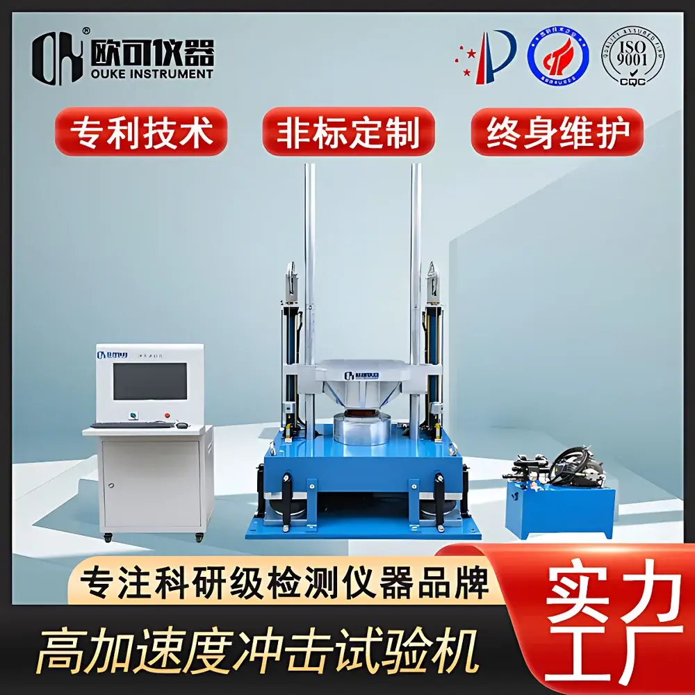
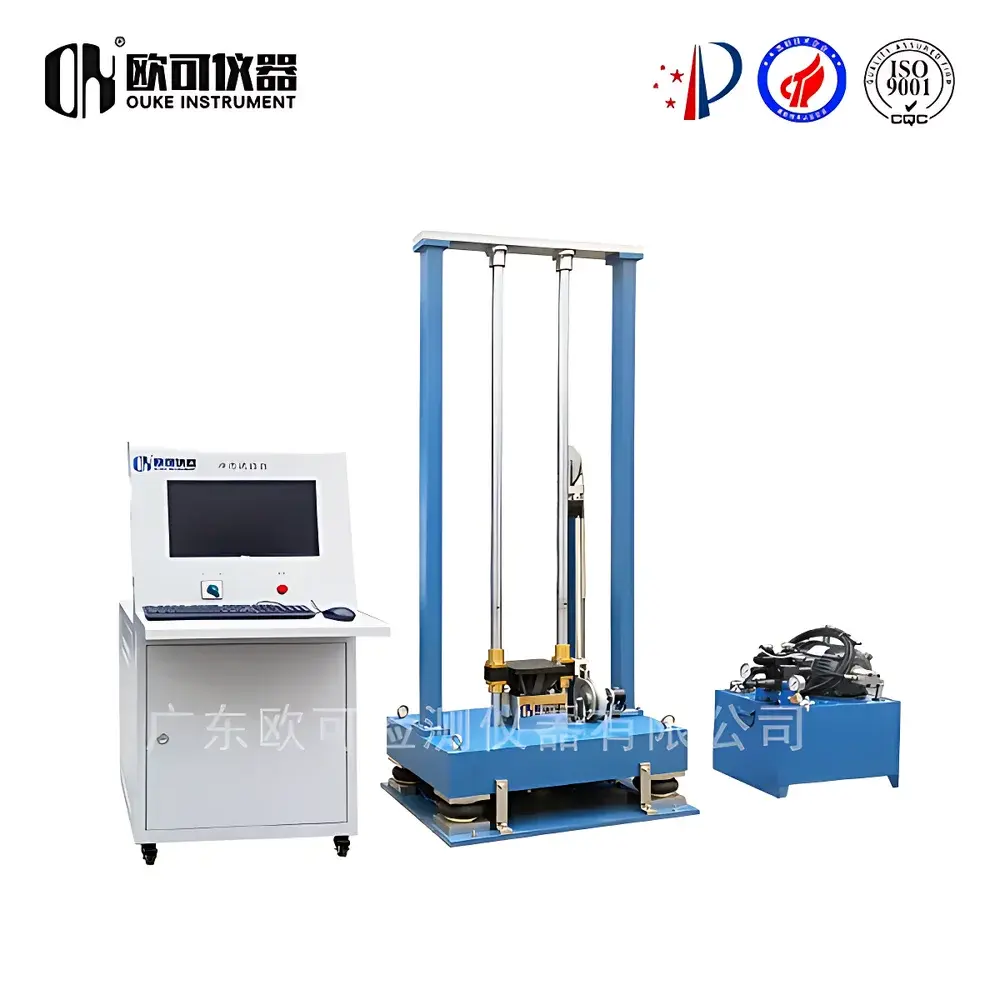
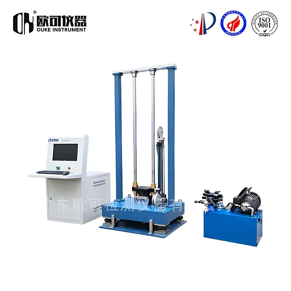
OK-S-14 High-Acceleration Shock Test System
| Brand | OK Instruments |
|---|---|
| Origin | Guangdong, China |
| Manufacturer Type | OEM/ODM Manufacturer |
| Country of Origin | China |
| Model | OK-S-14 |
| Instrument Category | Other Impact Testing Machines |
| Shock Acceleration | 1000 G |
| Impact Velocity | 4.5 m/s |
| Pendulum Moment (Impact Constant) | 380 N·m |
| Load Cell Range | 500 N |
| Maximum Lifting Height | 600 mm |
Overview
The OK-S-14 High-Acceleration Shock Test System is an electromechanically engineered test platform designed to generate controlled, transient mechanical shock pulses for reliability validation of components and assemblies under extreme deceleration conditions. It operates on the principle of rapid kinetic energy transfer: a driven table accelerates to a preset velocity (up to 4.5 m/s), then undergoes abrupt deceleration upon impact with a programmable pulse generator—producing calibrated acceleration profiles in the sub-10 ms domain. This methodology replicates real-world shock events such as drop impacts, transportation jolts, pyrotechnic separation forces, or battlefield-induced transients. Unlike quasi-static or low-frequency vibration testing, the OK-S-14 targets high-slew-rate dynamics where inertial loading dominates structural response—enabling detection of solder joint fractures, micro-cracks in ceramics, connector disengagement, and MEMS device stiction failure modes that remain invisible under conventional stress screening.
Key Features
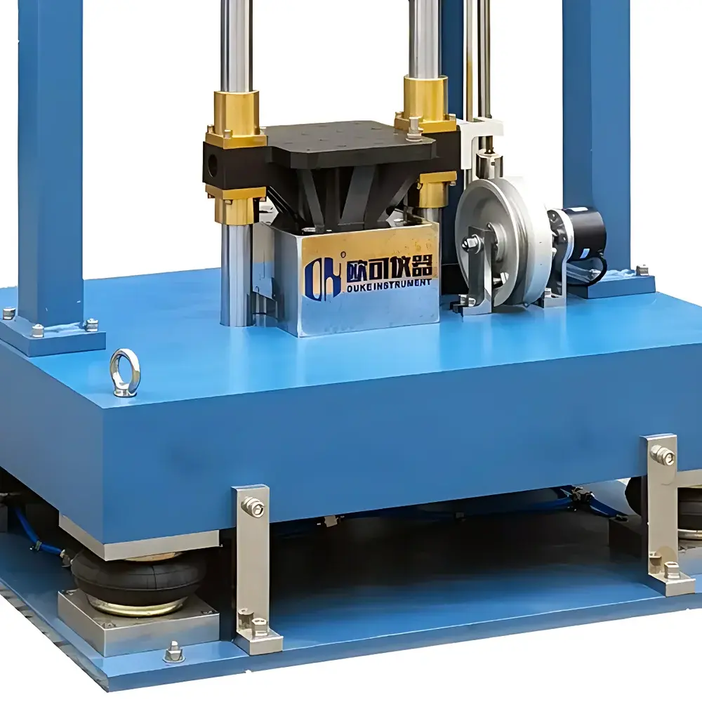
- Programmable shock pulse generation via interchangeable waveform shapers—including elastomeric (rubber, silicone), metallic (lead, aluminum), and composite damping inserts—to reproduce standardized half-sine, terminal-peak sawtooth, trapezoidal, and user-defined transient profiles.
- Robust rigid-frame construction with high-modal-stiffness baseplate and precision-machined impact surface, minimizing parasitic resonance and ensuring waveform fidelity across repeated cycles.
- Integrated high-resolution piezoelectric accelerometer (mounted directly on test table) coupled with 16-bit synchronized data acquisition system for real-time shock profile verification and closed-loop waveform adjustment.
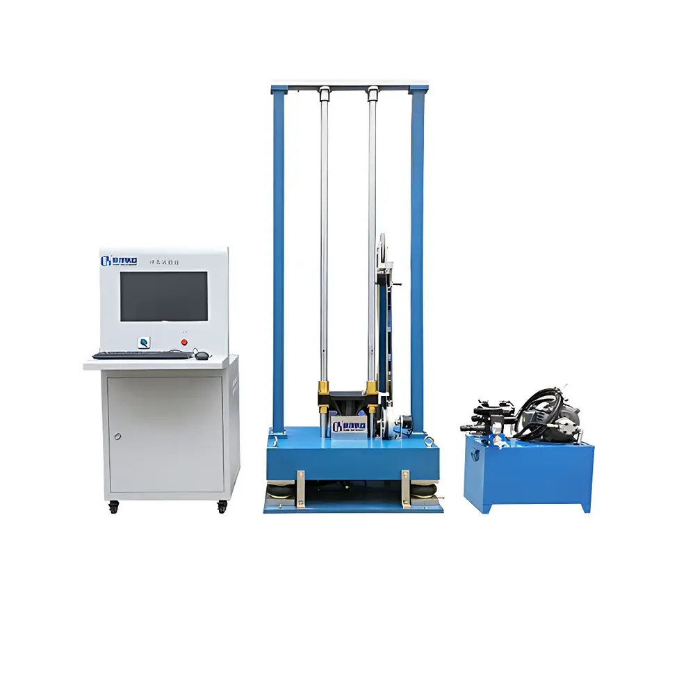
- Dual-mode actuation architecture: configurable for pneumatic-driven impact (optimized for high-energy, repeatable half-sine pulses) or free-fall mode (for ISTA-compliant packaging drop simulation up to 600 mm height).
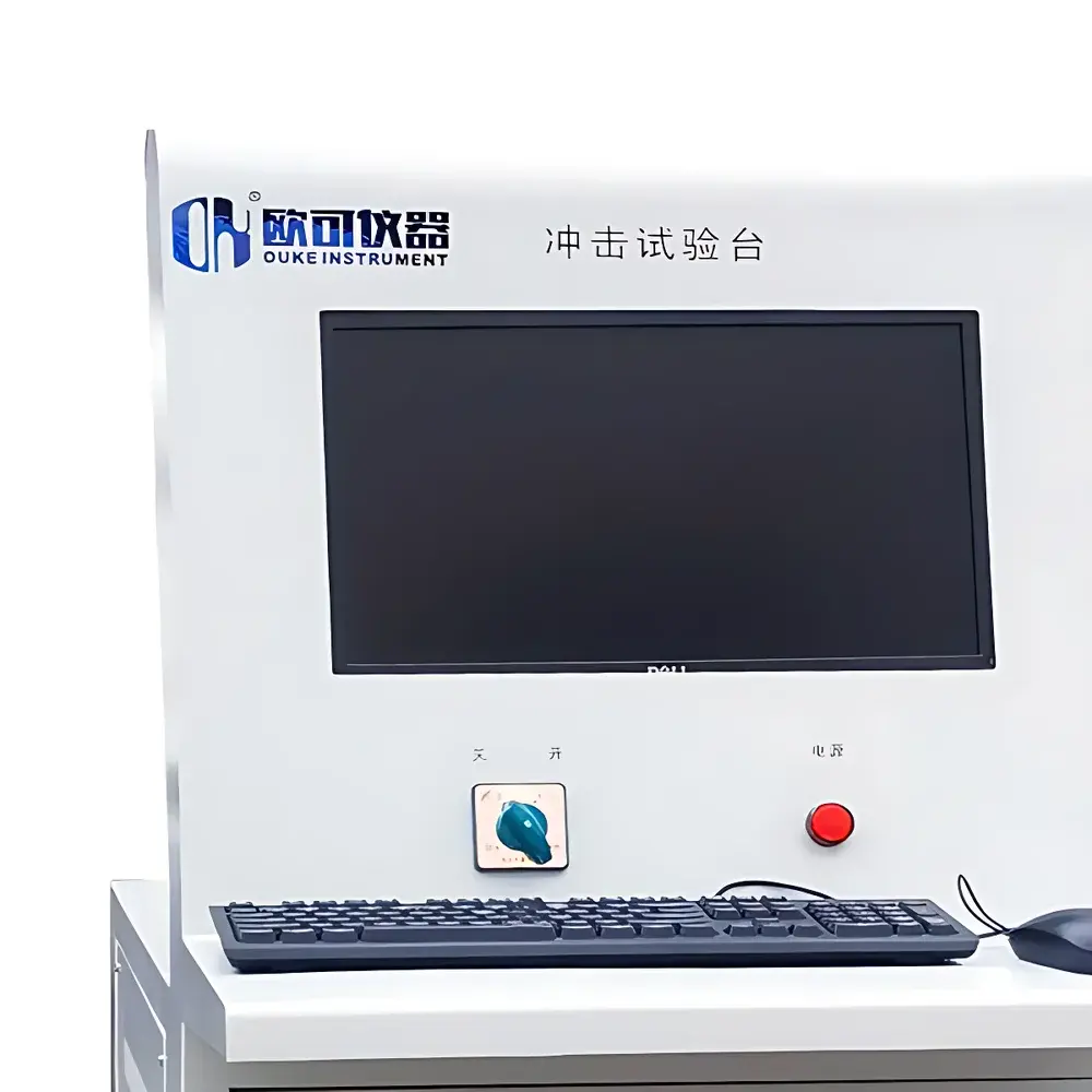
- Comprehensive control interface supporting parameter scripting—including peak acceleration (G-level), pulse duration (ms), rise time, number of shocks per sequence, dwell time between shocks, and pass/fail threshold monitoring.
Sample Compatibility & Compliance
The OK-S-14 accommodates specimens weighing up to 5 kg (customizable to 20 kg with reinforced mounting interface) on its 300 × 300 mm test surface. Mounting options include threaded inserts, vacuum chucks, and modular fixture plates compatible with MIL-STD-1377 and IEC 60068-2-27 Annex A fixtures. The system is validated against international shock test standards including IEC 60068-2-27 (Shock), MIL-STD-883 Method 2002.3 (Mechanical Shock), MIL-STD-202G Method 213 (Shock), and JESD22-B104F (Board-Level Drop Test). All shock event logs—including timestamped acceleration traces, sensor calibration metadata, and operator credentials—are stored with audit-trail integrity to support GLP/GMP traceability requirements.
Software & Data Management
The OK-S-14 is operated via OK-ShockControl v3.2—a Windows-based application compliant with FDA 21 CFR Part 11 for electronic records and signatures. The software enables waveform library management, real-time oscilloscope-style display of live acceleration data, automatic pass/fail evaluation against user-defined tolerance bands (±10% amplitude, ±15% duration), and export of raw .tdms or .csv files for third-party analysis (e.g., MATLAB, Python SciPy). Built-in report generation conforms to ISO/IEC 17025 documentation structure, including uncertainty budgeting for acceleration measurement (k=2, based on sensor sensitivity drift and DAQ linearity error).
Applications
- Electronics: Board-level drop testing of smartphones and wearables; qualification of BGA solder joints under shock-induced shear strain; validation of camera module alignment stability after transport shock.
- Automotive: Shock survivability assessment of ADAS sensors, airbag control units, and infotainment ECUs subjected to road-induced transient loads per ISO 16750-3.
- Aerospace & Defense: Pyroshock simulation for satellite payload release mechanisms; qualification of avionics enclosures per DO-160 Section 8.
- Packaging Engineering: ISTA 3A/3E-compliant transit simulation for e-commerce shipments; cushioning performance benchmarking using lead-impact or foam-anvil configurations.
- Industrial Components: Mechanical endurance verification of relays, push-button switches, and fiber-optic connectors under repeated high-G shock exposure.
FAQ
What shock waveforms can the OK-S-14 generate?
The system supports half-sine, terminal-peak sawtooth, trapezoidal, and custom user-loaded transient waveforms—achievable through physical pulse shaper selection and closed-loop velocity feedback control.
Does it comply with IEC 60068-2-27?
Yes—the OK-S-14 meets Class 1 (light-duty) and Class 2 (heavy-duty) shock severity levels defined in IEC 60068-2-27, with full traceable calibration certificates available upon request.
Can it be integrated with existing vibration test systems?
The mechanical interface and EtherCAT communication protocol allow seamless integration into multi-axis combined environment test systems (e.g., shock + random vibration), supporting MIL-STD-810H Method 516.7 sequencing.
Is remote operation and monitoring supported?
Via optional OPC UA server module, enabling secure SCADA integration, cloud-based test campaign orchestration, and real-time dashboard visualization through industry-standard IIoT platforms.
What maintenance is required for long-term waveform repeatability?
Scheduled quarterly verification includes accelerometer sensitivity recalibration, impact surface flatness inspection (≤5 µm deviation), and pneumatic cylinder seal integrity testing—documented in accordance with ISO/IEC 17025 preventive maintenance protocols.


