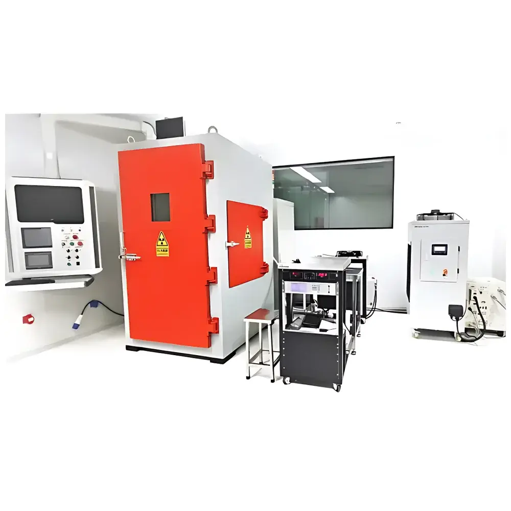
Aolong CHIRAD165 Wafer-Level X-Ray Irradiation System
| Brand | Aolong |
|---|---|
| Origin | Liaoning, China |
| Manufacturer Type | Manufacturer |
| Region Category | Domestic |
| Model | CHIRAD165 |
| Pricing | Upon Request |
| Max. X-ray Tube Voltage | 160 kV |
| Beam Angle | 40° |
| Max. System Power | 6000 W |
| Focal Spot Size | 5.5 mm |
| SSD (Source-to-Sample Distance) | OEM-defined |
| Dose Rate Range | >600 Gy/min |
| Real-time Dosimetry | Yes (dose rate, cumulative dose, irradiation time) |
| Cooling System | Integrated closed-loop heat exchanger |
| Stage | Motorized wafer stage with XYZ motion and ±45° rotation |
| Control System | PLC-based |
| Safety Interlocks | Door interlock + warning light |
| Chuck | Coaxial high-temperature vacuum chuck (OEM) |
| Microscope | PSM1000 stereomicroscope with 2-MP HDMI CCD (optional) |
| Microscope Stage | 2″ × 2″ XY travel |
| Vibration-Isolation Table | 900 mm × 800 mm (final dimensions subject to integration) |
| Probe Interface | 3-axis coaxial probe holder |
| Auxiliary Equipment | Air compressor included |
| Optional Accessories | Low/high-temperature coaxial chucks, semi-automated probe station, dry-air purge system |
Overview
The Aolong CHIRAD165 Wafer-Level X-Ray Irradiation System is an engineered platform designed for controlled, quantitative ionizing radiation exposure of semiconductor devices at the wafer and die level. It operates on the principle of bremsstrahlung X-ray generation via high-voltage electron bombardment of a tungsten or molybdenum target, delivering broadband photon spectra (typically 10–160 keV effective energy range) suitable for simulating total ionizing dose (TID) effects in microelectronic components. Unlike discrete-package irradiation systems, the CHIRAD165 integrates precision mechanical positioning, real-time dosimetric feedback, and vacuum-compatible thermal management—enabling irradiation under representative process-relevant conditions during pre-silicon design validation, post-fab characterization, and radiation-hardness assurance testing. Its architecture supports iterative test cycles aligned with JEDEC JESD57, ASTM F1892, and MIL-STD-883 Method 1019.8 protocols for TID evaluation.
Key Features
- High-power X-ray source with 160 kV maximum tube voltage and 6 kW rated output, enabling rapid dose delivery (>600 Gy/min) while maintaining beam stability across extended irradiation sessions.
- Motorized XYZ wafer stage with ±45° continuous rotation and fine Z-axis adjustment (micrometer resolution), facilitating oblique-angle irradiation and multi-site mapping without manual repositioning.
- Integrated coaxial high-temperature vacuum chuck (OEM-specified), supporting device operation up to 150 °C during irradiation—critical for accelerated stress testing and bias-conditioned TID analysis.
- Real-time dosimetry subsystem featuring calibrated ionization chamber and digital readout of instantaneous dose rate, cumulative dose, and elapsed time—traceable to national standards and compliant with ISO/IEC 17025-accredited calibration practices.
- PLC-based control architecture with programmable irradiation sequences, interlocked safety circuitry (door switch, emergency stop, status-indicating beacon), and audit-ready event logging.
- Dedicated vibration-isolated optical bench (900 mm × 800 mm) hosting PSM1000 stereomicroscope with 2-megapixel HDMI CCD, enabling in situ visual alignment of probe tips, bond pads, and active device areas prior to and during irradiation.
Sample Compatibility & Compliance
The CHIRAD165 accommodates full 200 mm (8″) wafers, partial wafers, diced dies on carriers, and packaged devices mounted on custom fixtures. Its modular chuck interface supports optional low-temperature (−65 °C) and high-temperature (up to 200 °C) variants, as well as dry-air purged environments to mitigate surface charging or oxidation during prolonged exposure. All operational parameters—including dose uniformity (±5% over 50 mm diameter field), beam hardening profile, and scatter contribution—are characterized per IEC 61000-4-5 and ANSI N42.22 guidelines. The system meets electromagnetic compatibility (EMC) Class B requirements and incorporates lead-shielded enclosure conforming to local radiation safety regulations (e.g., CNPC Regulation No. 122, GBZ 138–2002). Full documentation packages support GLP-compliant test reporting and FDA 21 CFR Part 11–aligned electronic records when integrated with validated LIMS or QMS platforms.
Software & Data Management
Control and monitoring are executed via a Windows-based HMI with deterministic timing loops ensuring sub-second synchronization between dose acquisition, stage motion, and environmental telemetry. All irradiation logs—including timestamped dose curves, stage coordinates, chuck temperature, vacuum level, and interlock events—are exported in CSV and XML formats compatible with MATLAB, Python (pandas), and industry-standard data analytics tools. Optional software modules provide automated dose uniformity mapping, cross-sectional dose profile reconstruction, and statistical process control (SPC) charting for batch-to-batch consistency assessment. Audit trails record user identity, parameter changes, and system state transitions with SHA-256 hashing—satisfying traceability requirements under ISO 9001:2015 Clause 8.5.2 and AS9100 Rev D.
Applications
- Radiation effect modeling: Generation of TID response datasets (e.g., threshold voltage shift ΔVth, leakage current increase Ioff) for compact model parameter extraction in BSIM, PSP, or EKV frameworks.
- Hardness-by-design validation: Early-stage screening of layout-level mitigation techniques (guard rings, enclosed geometry transistors) prior to tape-out.
- Process qualification: Evaluation of foundry-specific radiation tolerance across technology nodes (e.g., 28 nm FD-SOI vs. 65 nm bulk CMOS).
- Qualification testing: Support for space-grade component certification per ECSS-Q-ST-60-15C and NASA EEE-INST-002.
- Fundamental defect studies: Correlation of X-ray-induced trap generation kinetics with DLTS and CV profiling results.
FAQ
What is the minimum detectable dose rate and its uncertainty?
The integrated dosimeter achieves ±3% linearity from 0.1 Gy/min to >600 Gy/min, with type-A uncertainty <2.5% (k=2) at reference conditions (100 kV, 30 mA, 50 cm SSD). Calibration certificates are provided with each system.
Can the system perform spatially resolved irradiation?
Yes—motorized stage and collimated beam enable programmed raster scans with positional repeatability of ±1.5 µm, supporting localized irradiation of individual transistors or memory cells.
Is remote operation supported?
The PLC controller includes Ethernet/IP and Modbus TCP interfaces; secure remote access (SSH/VNC) can be enabled under customer-defined IT security policies.
How is beam filtration handled for spectrum tailoring?
Standard Cu or Al filters (0.5–2.0 mm thickness) are supplied; custom K-edge filters (e.g., Sn, Mo) can be integrated upon request to modify low-energy spectral content per application needs.
What maintenance intervals are recommended?
X-ray tube lifetime is rated ≥5000 hours at 80% max power; annual preventive maintenance includes dosimeter recalibration, cooling loop fluid analysis, and interlock functional verification per manufacturer’s service manual.


