Aolong X-ray Digital Real-time Imaging System
| Brand | Aolong |
|---|---|
| Origin | Liaoning, China |
| Manufacturer Type | OEM Manufacturer |
| Country of Origin | China |
| Model | X-ray Digital Real-time Imaging System |
| Pricing | Upon Request |
Overview
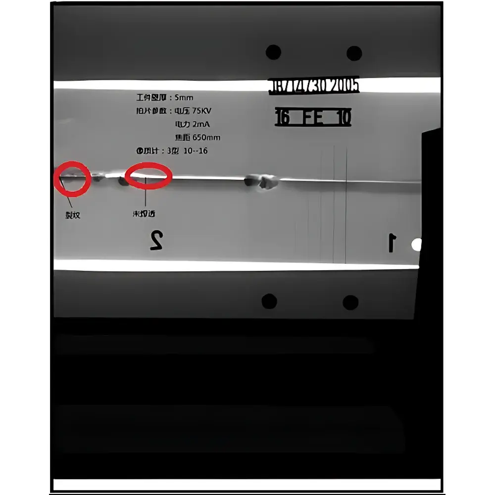
The Aolong X-ray Digital Real-time Imaging System is an industrial non-destructive testing (NDT) platform engineered for high-fidelity internal inspection of solid components without physical intervention. It operates on the fundamental principle of X-ray attenuation—where differential absorption of ionizing radiation by materials of varying density and atomic number generates contrast in transmitted images. Integrated with a high-frequency mobile or stationary X-ray generator, a high-resolution industrial television imaging chain, real-time digital image acquisition hardware, precision mechanical positioning subsystems, and certified radiation shielding architecture, the system delivers dynamic, frame-synchronized radiographic visualization. Designed for laboratory, production-line, and field-deployable NDT environments, it supports quantitative defect localization, dimensional metrology (within geometric magnification constraints), and structural integrity assessment under controlled exposure conditions.
Key Features
- Modular architecture integrating X-ray source, scintillator-based detector array, and real-time image processing electronics
- Real-time radiographic imaging at up to 30 fps (frame-per-second) with adjustable exposure parameters (kV, mA, pulse width)
- High spatial resolution enabled by micro-focus or mini-focus X-ray tubes (typical focal spot size ≤ 50 µm) and low-noise CMOS/CCD-based flat-panel detectors
- Comprehensive radiation safety compliance: fully interlocked lead-shielded enclosure meeting national GBZ 117–2020 and IEC 61331-1 standards for occupational dose limitation
- Motorized sample manipulation stage with XYZ translation and rotational capability (optional) for multi-angle tomographic acquisition
- Embedded calibration routines supporting grayscale linearity verification, geometric distortion correction, and detector uniformity mapping
Sample Compatibility & Compliance
The system accommodates metallic, ceramic, composite, and polymer specimens across a broad dimensional range—from small electronic packages ( 1 m height). Material thickness limits are governed by X-ray beam energy (typically 60–300 kV) and detector quantum efficiency; aluminum-equivalent penetration depth ranges from 20 mm (at 90 kV) to >120 mm (at 300 kV) depending on configuration. All operational protocols align with ISO 17636-2:2022 (radiographic testing of welds), ASTM E2698-21 (standard practice for radioscopic examination), and EN 462-1 for image quality indicator (IQI) sensitivity validation. System documentation supports GLP-compliant audit trails when operated under controlled procedural frameworks.
Software & Data Management
The proprietary acquisition and analysis software provides DICOM-compliant image capture, contrast enhancement (histogram equalization, unsharp masking), edge detection, and region-of-interest (ROI) measurement tools. Image sequences are stored in lossless PNG or compressed JPEG2000 format with embedded metadata (exposure time, tube voltage, detector gain, timestamp). For traceability, software logs all operator actions, parameter changes, and calibration events—enabling partial compliance with FDA 21 CFR Part 11 requirements when deployed with user authentication and electronic signature modules. Export options include CSV reports for defect coordinates, TIFF stacks for archival reconstruction, and PDF summary dossiers suitable for QA documentation.
Applications
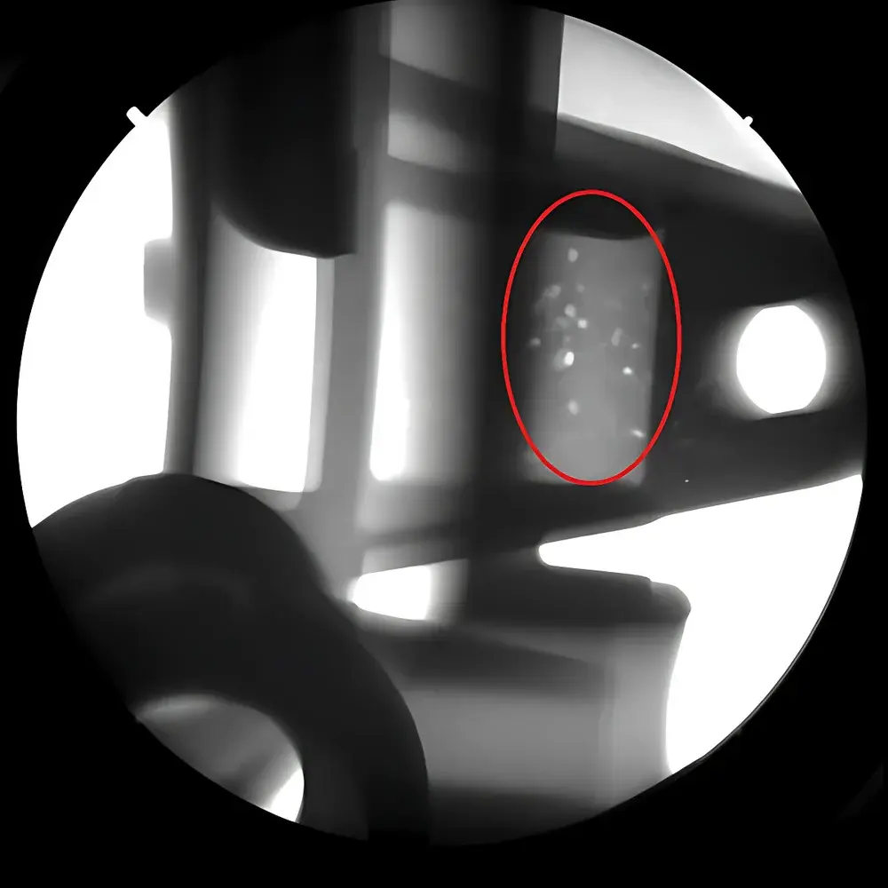
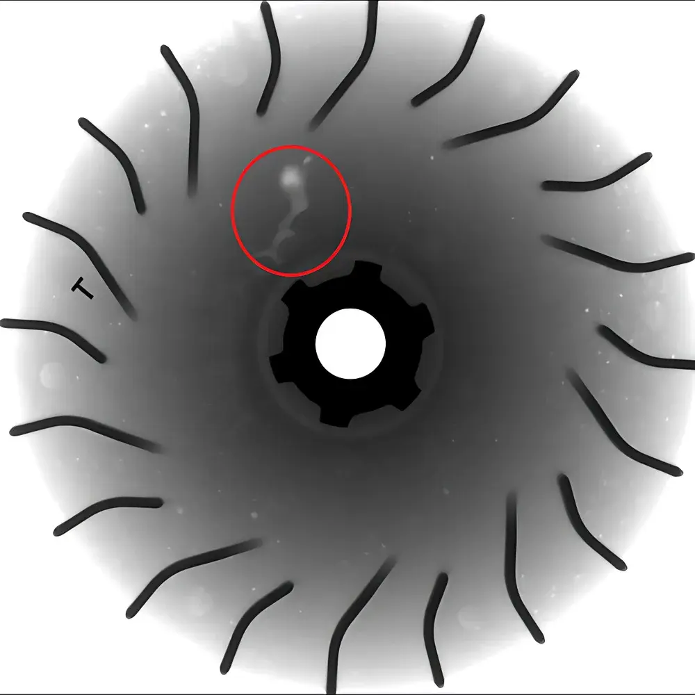
- Defect detection: porosity, inclusions, cracks, lack-of-fusion in castings, welds, and additive-manufactured parts
- Failure analysis: root cause identification in field-return components via comparative radiograph overlay
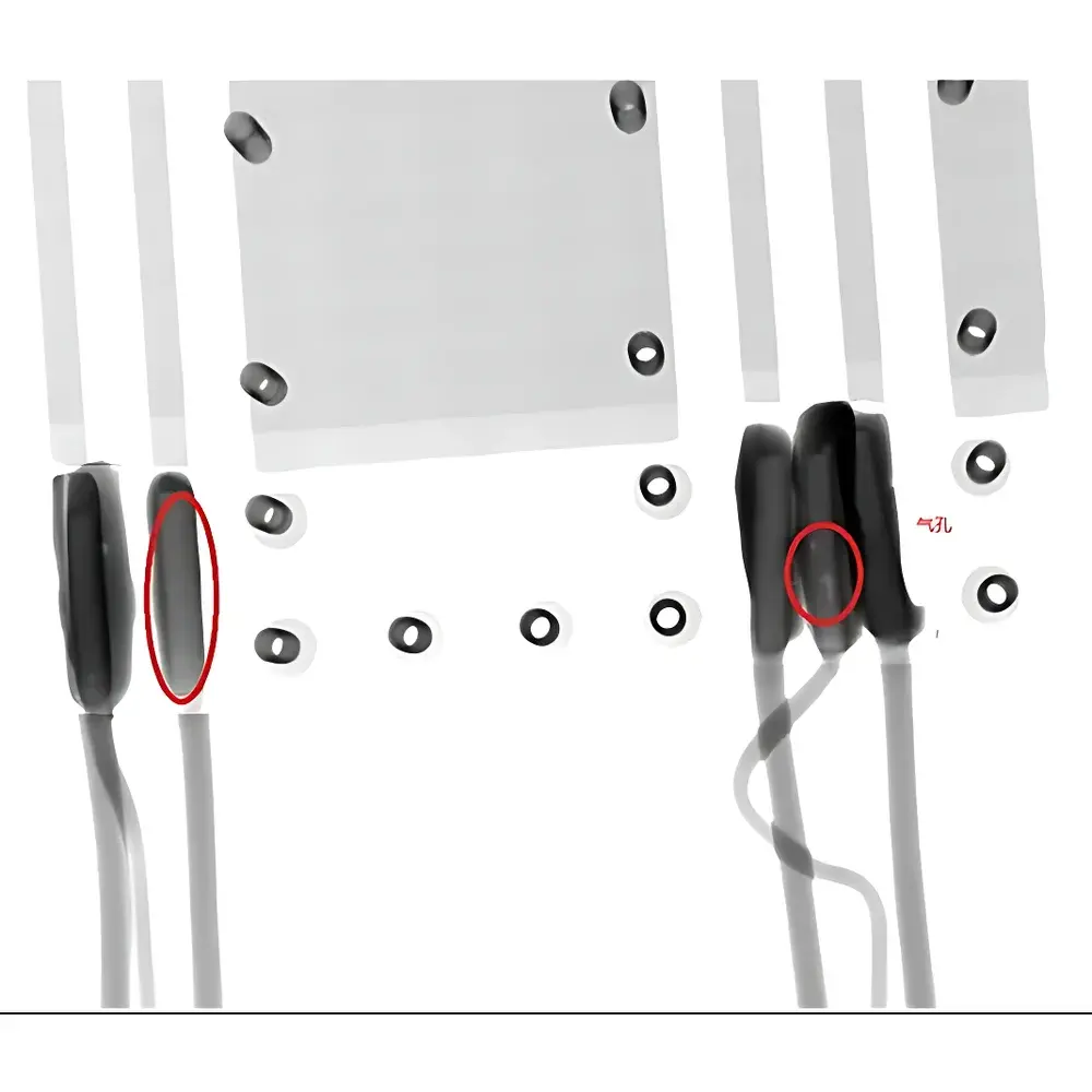
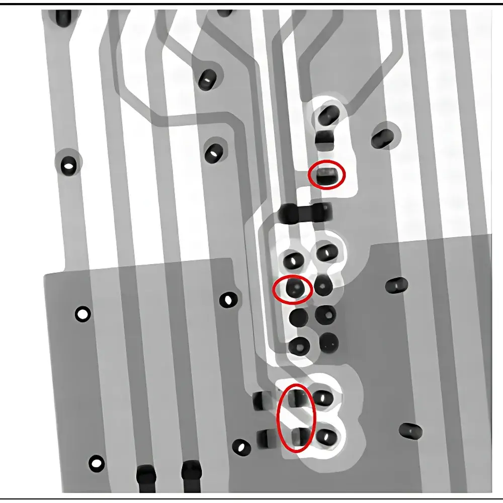
- Process validation: monitoring filler distribution in encapsulated electronics or adhesive bondline integrity in aerospace assemblies
- Dimensional verification: wall thickness mapping, void volume quantification, and assembly verification (e.g., presence/position of internal fasteners)
- Reliability screening: high-reliability component acceptance testing per MIL-STD-883 or JEDEC JESD22 standards
- Regulatory support: evidence generation for ASME BPVC Section V, API RP 1104, and EN 13663 certification submissions
FAQ
What is the typical spatial resolution achievable with this system?
Resolution depends on geometric magnification, focal spot size, and detector pixel pitch; under optimal setup (≥5× magnification), effective resolution is typically 5–20 µm.
Can the system perform computed tomography (CT)?
Yes—when equipped with a rotary stage and compatible reconstruction software, it supports cone-beam CT acquisition for 3D volumetric analysis.
Is regulatory documentation provided for installation and operation?
Yes—includes radiation safety certification, CE-marking documentation (for export models), electrical safety test reports, and IQ/OQ validation templates.
How is system calibration maintained over time?
Daily warm-up and reference image acquisition are recommended; annual third-party radiation output calibration and detector linearity verification are advised per ISO/IEC 17025 guidelines.
Does the system support automated defect recognition (ADR)?
Basic threshold-based segmentation is included; AI-driven ADR modules are available as optional add-ons compliant with ISO/IEC TR 24028:2020 on AI trustworthiness.


