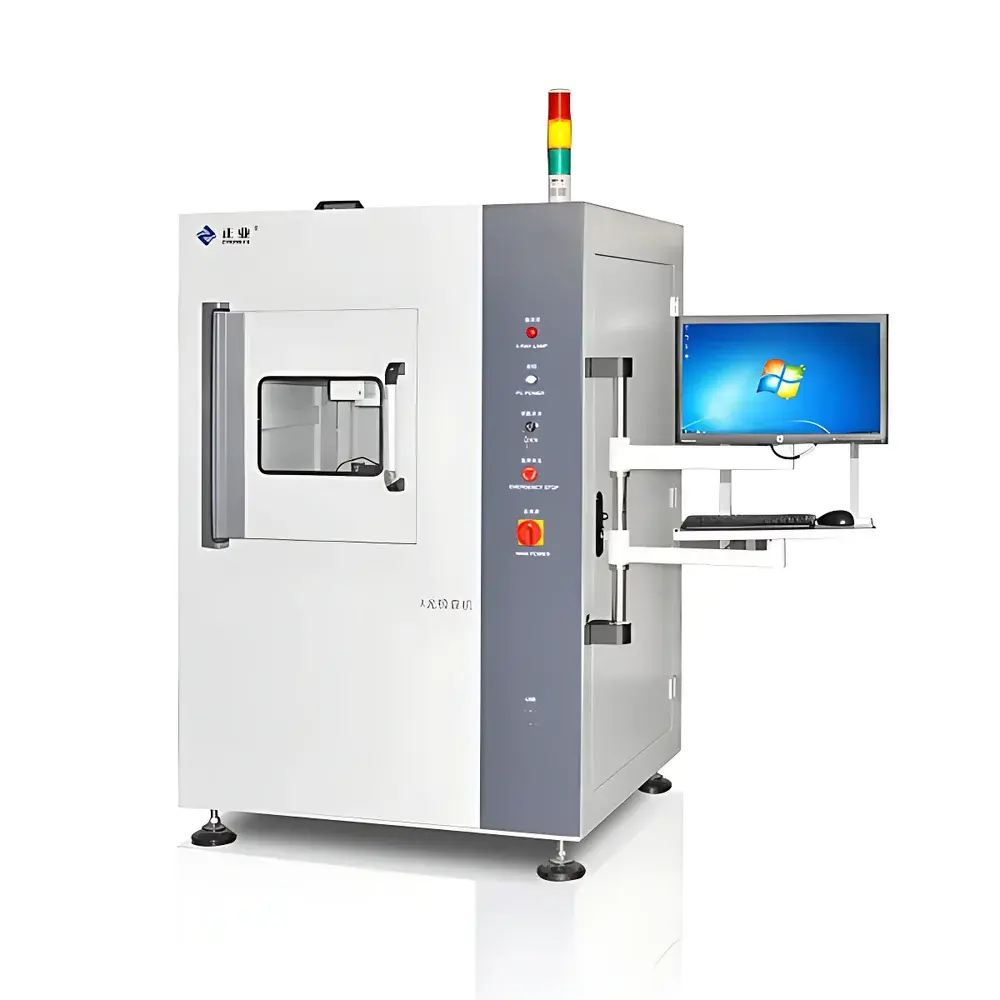
Astroda XG5 PCB Solder Joint X-ray Inspection System
| Brand | Astroda |
|---|---|
| Origin | Guangdong, China |
| Model | XG5 |
| Price Range | USD 70,000 – 140,000 |
| Category | X-ray Radiographic Inspection System for Electronics Assembly |
| Detection Principle | Transmission X-ray Imaging (2.5D) |
| Motion Control | CNC-programmable XYZ-axis movement of X-ray source and image intensifier |
| Image Acquisition | Real-time digital radiography with software-based measurement and pass/fail classification |
| Compliance | Designed to support IPC-A-610, IPC-J-STD-001, and ISO 9001 quality audit workflows |
| Software | Proprietary automated inspection suite with measurement tools (linear distance, circle diameter, concentricity, point-to-center), navigation mapping, and DICOM-compatible image export |
Overview
The Astroda XG5 PCB Solder Joint X-ray Inspection System is a high-resolution, transmission-based digital radiographic inspection platform engineered for non-destructive evaluation of printed circuit board (PCB) assemblies. It operates on the fundamental principle of differential X-ray attenuation: when a collimated X-ray beam passes through a sample, variations in material density and thickness produce contrast in the resulting radiograph captured by a high-sensitivity image intensifier or flat-panel detector. The system delivers 2.5D inspection capability—enabling precise planar measurements with Z-axis positional awareness—without requiring full computed tomography (CT) reconstruction. This makes it particularly suitable for production-floor deployment in electronics manufacturing, where rapid, repeatable assessment of solder joint integrity (e.g., voiding, bridging, insufficient wetting, tombstoning, hidden pad lift) is critical to first-pass yield and field reliability. Unlike generic industrial radiography systems, the XG5 is purpose-built for microelectronic packaging geometries, supporting fine-pitch components down to 0201 and BGAs with pitch ≤ 0.4 mm.
Key Features
- CNC-driven XYZ motion architecture: Independent motorized positioning of the X-ray tube and image intensifier enables precise geometric alignment and consistent magnification control across multiple inspection points.
- Proprietary automated measurement engine: Supports calibrated linear distance, circle diameter, concentricity, radial offset, and multi-point geometric referencing—each traceable to NIST-traceable calibration standards applied during factory setup.
- Real-time navigation interface: A large-field-of-view overview map displays the entire PCB layout; clicking any region triggers synchronized stage movement to that coordinate, reducing operator dependency and minimizing setup time per board.
- Stable mechanical design: Precision-ground ball screws, synchronous belt-driven stepper motors, and rigid aluminum-alloy frame ensure sub-micron repeatability in repeated positioning (±2 µm typical over 100 cycles).
- Digital image processing pipeline: On-the-fly contrast enhancement, edge sharpening, noise suppression, and dynamic range optimization preserve defect visibility without compromising measurement linearity.
Sample Compatibility & Compliance
The XG5 accommodates standard PCB formats up to 400 × 300 mm, with optional custom fixtures for panelized or flex-rigid assemblies. It supports both single-sided and double-sided boards, including those with shielding layers, thermal pads, and embedded passive components. All measurement outputs comply with IPC-A-610 Class 2 and Class 3 acceptance criteria for solder joint evaluation. Audit-ready reporting includes timestamped images, measurement logs with operator ID, and configurable pass/fail thresholds—structured to align with ISO 9001 internal audit requirements and support GLP-aligned documentation practices. While not certified to IEC 62471 or FDA 21 CFR Part 1020.40, the system incorporates interlocked shielding, real-time dose monitoring, and automatic beam cutoff during door opening—meeting standard occupational safety guidelines for low-energy cabinet X-ray systems (< 160 kVp).
Software & Data Management
The bundled inspection software runs on Windows 10 IoT Enterprise and provides role-based user access control (operator, engineer, administrator). Measurement data is stored in SQLite databases with optional ODBC export for integration into MES or SPC platforms. Image archives follow DICOM 3.0 conventions, enabling interoperability with enterprise PACS or QA document management systems. All software actions—including parameter changes, measurement executions, and report generation—are logged with timestamps and user identifiers to satisfy basic ALCOA+ data integrity principles. Customizable templates allow batch programming for recurring board types, and measurement results can be exported as CSV, PDF, or XML for statistical process control analysis.
Applications
- Solder joint void analysis in QFN, BGA, and LGA packages
- Wire bond integrity verification in power modules and RF assemblies
- Internal layer alignment validation in multilayer HDI substrates
- Component placement verification (e.g., polarity, rotation, coplanarity)
- Failure analysis root cause identification in returned field units
- Process qualification and DOE support for reflow profile optimization
FAQ
What is the maximum detectable void size in solder joints?
Detection limit depends on geometry, material composition, and imaging geometry—but under optimal conditions (5× geometric magnification, 90 kVp, Cu filter), sub-25 µm voids are resolvable in SnAgCu solder on FR-4 substrates.
Does the system support automated pass/fail classification?
Yes—threshold-based rules can be defined per measurement type (e.g., “void area > 25% of solder volume → fail”) and applied across batches with visual flagging and summary reporting.
Is external calibration required annually?
Factory calibration is performed using certified gauge blocks and step wedges; users are advised to perform quarterly verification checks using the included reference phantom—full recalibration is recommended every 12 months or after major mechanical service.
Can the system integrate with factory automation protocols?
It supports Modbus TCP and OPC UA for status signaling and basic trigger/control; custom API integration (REST/JSON) is available under NDA for advanced MES synchronization.


