Auniontech COMS Magview Magnetic Field Imaging Camera (MOI)
| Brand | Auniontech |
|---|---|
| Model | COMS Magview |
| Sensor Types | Type A–E |
| Max Sensor Area | 45 × 60 mm |
| Spatial Resolution | Up to 15 µm |
| Measurement Time | ≤1 s |
| Field Range | Up to 1 T (Type E) |
| Imaging Principle | Faraday Effect-based Magneto-Optic Imaging |
| Software | COMS-Magview Analysis Suite |
| Compliance | Supports GLP-aligned data traceability, ASTM E1444-compliant magnetic inspection workflows |
Overview
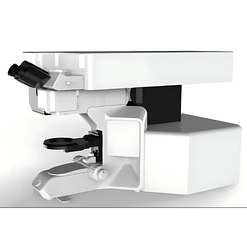
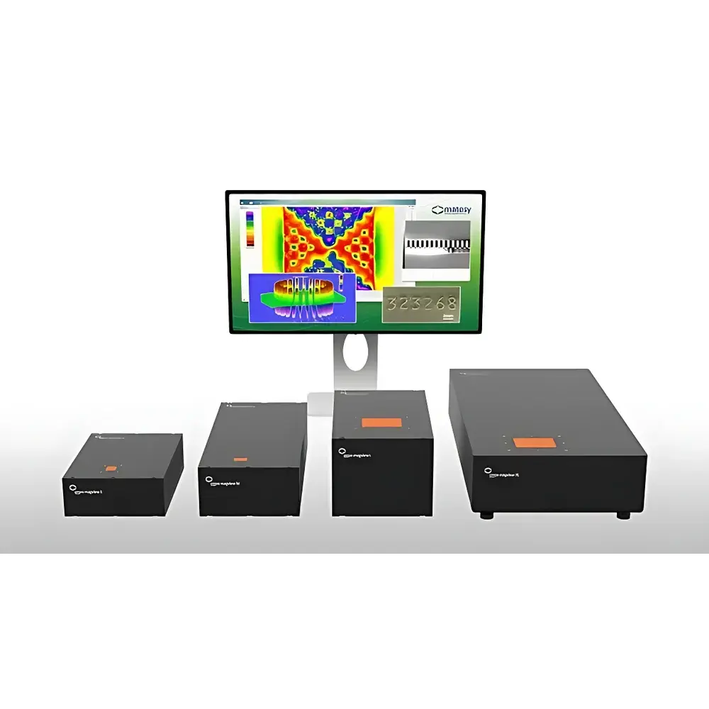
The Auniontech COMS Magview Magnetic Field Imaging Camera is a precision magneto-optic imaging (MOI) system engineered for non-contact, two-dimensional visualization and quantitative mapping of magnetic flux density distributions across surfaces of magnetic and ferromagnetic materials. Operating on the physical principle of the Faraday effect—where linearly polarized light undergoes rotation proportional to the component of magnetic induction parallel to the optical path—the system converts local magnetic field vectors into high-fidelity grayscale or false-color intensity maps. Unlike conventional Hall probe arrays or scanning SQUID systems, the COMS Magview delivers full-field, single-shot acquisition with no mechanical scanning, enabling real-time observation of dynamic magnetic phenomena such as domain wall motion, eddy current distribution, and magnetization reversal processes. Designed for integration into both industrial QA/QC environments and advanced research laboratories, it supports rapid, repeatable assessment of magnetic integrity without sample preparation or electrical contact.
Key Features
- Full-field, snapshot magnetic imaging with acquisition times ≤1 second per frame
- Selectable sensor modules (Types A–E) optimized for distinct field ranges, material classes, and resolution requirements
- Maximum active sensor area up to 45 × 60 mm, enabling macro-scale inspection of large components (e.g., motor laminations, magnetic encoders, weapon chassis)
- Spatial resolution down to 15 µm—achievable through high-magnification optics and low-noise CMOS imaging architecture
- Quantitative Bz mapping calibrated against traceable NIST-traceable reference fields
- Integrated dual-polarizer optical train with temperature-stabilized magneto-optic indicator film (e.g., TbGdFe or Bi-substituted YIG)
- Ruggedized optomechanical housing compliant with ISO 14644-1 Class 8 cleanroom handling protocols
Sample Compatibility & Compliance
The COMS Magview accommodates diverse sample geometries—including flat sheets, curved substrates, assembled subcomponents, and irregularly shaped parts—without requiring conductive coating or vacuum conditions. It is routinely deployed in accordance with ASTM E1444 (Standard Practice for Magnetic Particle Testing) for surface-breaking flaw detection in ferrous alloys, and supports internal validation protocols aligned with ISO/IEC 17025 for accredited magnetic measurement laboratories. For regulated industries, the system’s software audit trail functionality complies with FDA 21 CFR Part 11 requirements when configured with user authentication, electronic signatures, and immutable data archiving. Applications span electric motor core lamination analysis (IEC 60404-6), magnetic encoder verification (ISO/IEC 19794-5), forensic document examination (EN 13847), and residual magnetism screening in aerospace fasteners (SAE AMS 2750).
Software & Data Management
The COMS-Magview Analysis Suite provides a modular, scriptable environment for image preprocessing, vector field reconstruction, statistical parametric mapping, and automated defect classification. Core capabilities include background subtraction, spatial filtering, Bz gradient calculation, domain boundary detection via Canny edge algorithms, and time-series correlation for dynamic field evolution studies. All processed datasets are stored in HDF5 format with embedded metadata (sensor calibration coefficients, environmental timestamps, operator ID), ensuring full traceability. Export options include CSV, TIFF (16-bit), and MATLAB .mat files. Optional API integration enables linkage with MES platforms (e.g., Siemens Opcenter) and LIMS systems for automated report generation and SPC charting.
Applications
- Quality assurance of electrical steel sheets: detection of localized permeability anomalies, grain orientation deviations, and insulation layer defects
- Non-destructive evaluation of permanent magnets: identification of demagnetized zones, crack-induced field leakage, and multi-pole alignment errors
- Forensic analysis of magnetic security features: verification of banknote magnetic ink patterns, tamper-evident label integrity, and erased serial number recovery
- Development and validation of magnetic encoders: verification of pole pitch uniformity, field amplitude consistency, and angular error mapping
- Research in soft magnetic composites: visualization of interparticle flux bridging, hysteresis loop spatial heterogeneity, and thermal aging effects
- Defense applications: magnetic signature profiling of naval vessels, stealth component screening, and magnetic anomaly detection (MAD) sensor calibration
FAQ
What physical principle enables magnetic field visualization in the COMS Magview?
The system relies on the magneto-optic Faraday effect: magnetic flux density modulates the polarization state of transmitted light through a birefringent indicator film; this change is converted into intensity variation via an analyzer polarizer.
Can the COMS Magview measure fields above 1 Tesla?
Type E sensors support up to 1 T in static DC fields; for higher fields (>1 T), external flux concentration via soft magnetic yokes or custom pole pieces is required to maintain linearity and avoid sensor saturation.
Is calibration traceable to national standards?
Yes—each sensor module is factory-calibrated using Helmholtz coils referenced to NIST-traceable fluxgate magnetometers; calibration certificates include uncertainty budgets per ISO/IEC 17025 Annex A.
How is geometric distortion corrected during image analysis?
A two-step correction protocol applies lens distortion modeling (via Zhang’s method) followed by pixel-wise Bz interpolation using a pre-characterized sensor response matrix derived from grid-based field mapping.
Does the system support automated pass/fail decision logic for production lines?
Yes—the Analysis Suite includes rule-based thresholding engines and machine learning classifiers (SVM, random forest) trainable on labeled defect libraries; outputs integrate directly with PLC-triggered reject mechanisms.