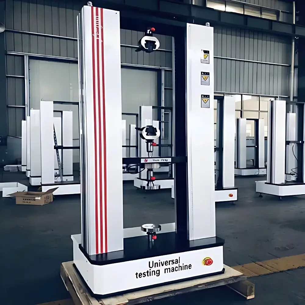
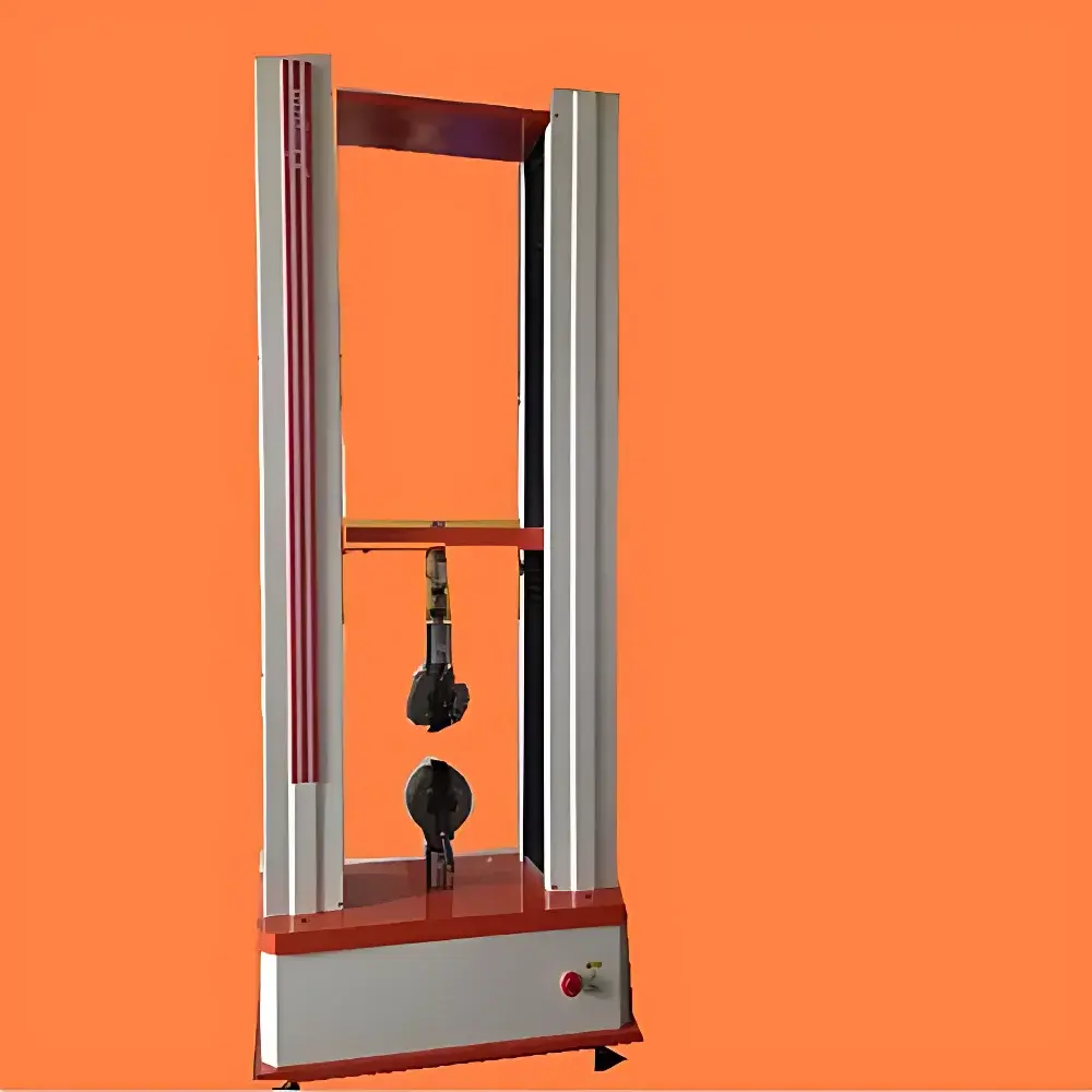
Beiguang Jingyi BWN-2500N Electronic Universal Testing Machine
| Brand | Beiguang Jingyi / All Precision Instrument |
|---|---|
| Origin | Beijing, China |
| Manufacturer Type | Direct Manufacturer |
| Product Category | Domestic (China-made) |
| Model | BWN-2500N |
| Instrument Type | Electronic Universal Testing Machine |
| Maximum Test Load | 5000 N |
| Force Measurement Range | 2–10% of Full Scale |
| Displacement Resolution | 0.01 mm |
| Power Supply | ~220 V ±10%, 50 Hz, 0.5 kW |
| Force Repeatability Error | ≤1% |
| Zero Load Error | ±0.1% |
| Speed Range | 0.05–500 mm/min |
| Speed Accuracy | Better than ±1% |
| Effective Tensile Stroke | 700 mm |
| Force Indication Error | Better than ±1% |
Overview
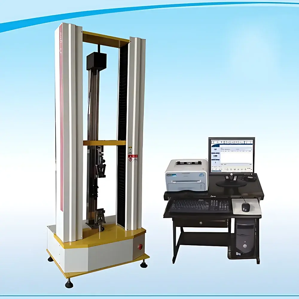
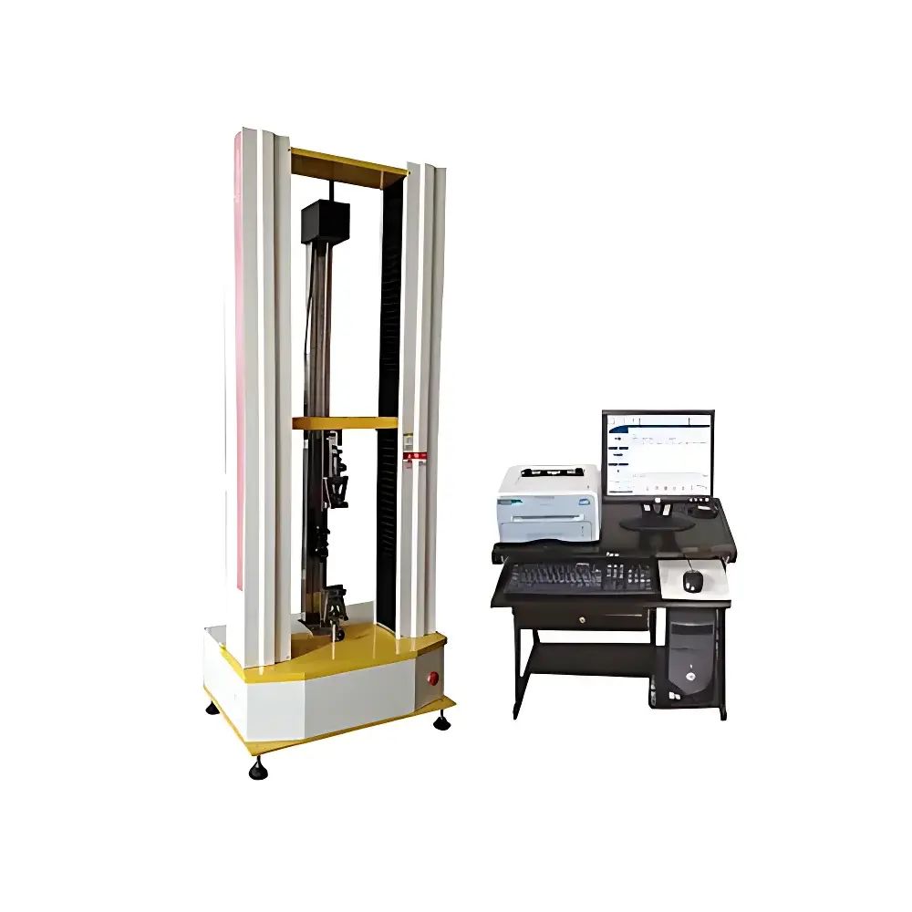
The Beiguang Jingyi BWN-2500N Electronic Universal Testing Machine is an electromechanical force-testing system engineered for precision mechanical property evaluation of materials under uniaxial tension, compression, bending, and shear loading conditions. It operates on the principle of servo-controlled electromechanical actuation, where a high-accuracy ball screw-driven crosshead applies controlled displacement or load to a specimen while synchronized sensors continuously acquire force and displacement data. Designed in accordance with ISO 7500-1 (static calibration of testing machines) and ASTM E4 (standard practices for force verification), the system delivers traceable, reproducible results suitable for QC laboratories, R&D centers, and academic institutions conducting standardized mechanical tests per ASTM D638, ISO 527, ASTM C39, ISO 3344, and GB/T 228.1. Its modular architecture supports interchangeable fixtures—including compression platens, tensile grips, and bending jigs—enabling full compliance with material-specific test protocols across polymers, metals, composites, elastomers, and ceramics.
Key Features
- High-resolution optical encoder-based displacement measurement with 0.01 mm resolution, ensuring precise stroke tracking across the full 700 mm effective tensile space.
- Embedded microcontroller-based control system with integrated test software for real-time acquisition, calculation, and display of stress, strain (with optional extensometer), tensile strength, yield point, elastic modulus, and elongation at break.
- Wide-speed digital servo drive (0.05–500 mm/min) with <±1% speed accuracy, powered by a low-noise precision reduction gearbox and preloaded ball screw assembly for smooth, vibration-free operation.
- Dual-mode control capability: load-controlled and displacement-controlled testing, with automatic switching between phases during multi-stage tests.
- Robust mechanical design featuring self-aligning universal joints and crosshead leveling (≤0.2/1000) to maintain axial alignment and minimize bending moments during specimen loading.
- Comprehensive hardware protection: over-load, over-current, over-voltage, and travel-limit safeguards prevent damage during abnormal operation or operator error.
- Compression platen specifications comply with ISO 376 requirements: hardened surfaces (≥55 HRC), surface roughness Ra ≤ 0.80 µm, concentric alignment markers, and spherical seat functionality for uniform load distribution.
Sample Compatibility & Compliance
The BWN-2500N accommodates standard and custom specimens up to 5000 N maximum load capacity. Tensile specimens conform to ASTM D638 Type I–V, ISO 527-2, and GB/T 1040 geometries; compression samples meet ASTM C39 (concrete), ISO 604 (rigid plastics), and GB/T 1447 (fiberglass) dimensions. The machine’s force transducer is calibrated to ISO 7500-1 Class 1 accuracy, and its displacement system meets ISO 20282 resolution criteria. All test reports generated include metadata required for GLP/GMP environments, including operator ID, timestamp, environmental conditions (optional external sensor input), and audit-trail-enabled calibration history. While not FDA 21 CFR Part 11 certified out-of-the-box, the system supports third-party validation packages for regulated pharmaceutical or medical device testing.
Software & Data Management
The native Windows-based software provides intuitive workflow navigation through four core interfaces: test method selection, parameter configuration, real-time test monitoring, and post-test analysis. During testing, dual-channel dynamic curves (load vs. time, load vs. displacement) are rendered in real time with adjustable scaling and overlay capability. Post-test, users may zoom into critical regions (e.g., yield plateau or fracture onset), recompute derivatives (e.g., tangent modulus), and export annotated graphs as PNG or SVG. Raw data is saved in CSV format; summary reports are exportable to Microsoft Word and Excel for integration into LIMS or QA documentation systems. All data files include embedded metadata (test ID, operator, date/time, machine serial number, calibration certificate ID) to support ISO/IEC 17025 traceability requirements.
Applications
This system serves as a primary tool for mechanical characterization in diverse industrial sectors. In polymer manufacturing, it quantifies tensile strength, elongation, and flexural modulus of injection-molded parts and extruded films. In construction materials labs, it performs compressive strength testing of mortar, grout, and lightweight concrete per ASTM C109 and EN 12390-3. For quality assurance in wire, cable, and fastener production, it verifies breaking load, proof load, and permanent set behavior. Academic researchers employ it for constitutive modeling of biomaterials, hydrogels, and 3D-printed lattice structures. Optional accessories—including pneumatic grips, environmental chambers (-40°C to +200°C), and video extensometry—extend its utility into advanced deformation studies.
FAQ
Why does the display remain blank after power-on?
Verify mains voltage (220 V ±10%) and check integrity of the internal fuse.
Why does the crosshead fail to move upward when the “Raise” command is issued?
Confirm proper connection of control cables, inspect upper travel limit switch status, and verify power supply to the frequency converter.
Why does the display show “Sensor Not Connected” or “Overload”?
Ensure secure mating of the load cell connector, validate sensor functionality via substitution, and perform zero-point recalibration if drift is suspected.
Why does the thermal printer feed blank paper or fail to advance?
Confirm correct orientation and thermal sensitivity of installed paper; verify rotation of the rubber feed roller upon manual activation of the print command.
Why can’t full-scale calibration be completed successfully?
A shifted zero offset in the load cell may require hardware-level null adjustment prior to software calibration—refer to Section 4.2 of the Technical Manual for procedure.


